


Application – Three-Phase Motors
9. Controls-Soft Starters and VFDs: Reduced voltage
starters and variable speed drives (inverter drives)
may be used with Franklin three-phase submersible
motors to reduce starting current, upthrust, and
mechanical stress during start-up. The guidelines
for their use with submersible motors are different
than with normal air cooled motor applications.
Refer to the Franklin Electric Application, Installation
and Maintenance (AIM) Manual Reduced Voltage
Starters section or Variable Speed Submersible
Pump Operation, Inverter Drives sections for specifi c
details including required fi ltering.
10. Motor Overload Protection: Submersible motors
require properly sized ambient compensated
Class 10 quick-trip overloads per Franklin’s AIM
Manual guidelines to protect the motor. Class 20
or higher overloads are NOT acceptable. Franklin’s
SubMonitor is strongly recommended for all large
submersibles since it is capable of sensing motor
heat without any additional wiring to the motor.
Applications using Soft Starters with a SubMonitor
require a start-up bypass - consult the factory for
details. SubMonitor can not be used in applications
using a VFD control.
11. Motor Surge Protection: Properly sized, grounded
and dedicated motor surge arrestors must be
installed in the supply line of the booster module as
close to the motor as possible. This is required on
all systems including those using soft-starters and
variable speed drives (inverter drives).
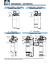
12. Wiring: Franklin’s lead assemblies are only sized
for submerged operation in water to the motor
nameplate maximum ambient temperature and
may overheat and cause failure or serious injury
if operated in air. Any wiring not submerged must
meet applicable national and local wiring codes and
Inline Booster Pump Systems (continued)
Franklin Cable Chart tables 16-21. (Notice: wire size,
wire rating and insulation temperature rating must be
known when determining its suitability to operate in
air or conduit. Typically, for a given size and rating,
as the insulation temperature rating increases its
ability to operate in air or conduit also increases.)
13. Check Valves: Spring-loaded check valves must
be used on start-up to minimize motor upthrusting,
water hammer, or in multiple booster (parallel)
applications to prevent reverse fl ow.
14. Pressure Relief Valves: A pressure relief valve is
required and must be selected to ensure that, as the
pump approaches shut-off, it never reaches the point
that the motor will not have adequate cooling fl ow
past it.
15. System Purge (Can Flooding): An air bleeder
valve must be installed on the booster sleeve so that
fl ooding may be accomplished prior to booster start-
up. Once fl ooding is complete, the booster should
be started and brought up to operating pressure as
quickly as possible to minimize the duration of an
upthrust condition. At no time should air be allowed
to gather in the booster sleeve because this will
prevent proper cooling of the motor and permanently
damage it.
16. System Flush – Must Not Spin Pump: Applications
may utilize a low fl ow fl ushing operation. Flow
through the booster sleeve must not spin the pump
impellers and the motor shaft. If spinning takes
place, the bearing system will be permanently
damaged and the motor life shortened. Consult the
booster pump manufacturer for maximum fl ow rate
through the pump when the motor is not energized.
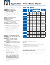
Based on 30 °C maximum ambient with cable length of 100 feet or less.
Table 37 Franklin Cable chart (See 12. Wiring)
CABLE
TEMP.
RATING
(°C)
MOTOR NAME-
PLATE RATED
AMPS FULL
LOAD
#10 AWG #8 AWG #6 AWG #4 AWG #2 AWG
SOURCE OF CABLE
AMPACITY
IN AIR
IN
CONDUIT
IN AIR
IN
CONDUIT
IN AIR
IN
CONDUIT
IN AIR
IN
CONDUIT
IN AIR
IN
CONDUIT
75
3-LEAD (DOL)
40A 28A 56A 40A 76A 52A 100A 68A 136A 92A
US N.E.C., 2002 edition,
tables 310.16 & 310.17
6-LEAD (Y-∆)
69A 48A 97A 69A 132A 90A 173A 118A 236A 19A
90
3-LEAD (DOL)
44A 32A 64A 44A 84A 60A 112A 76A 152A 104A
US N.E.C., 2002 edition,
tables 310.16 & 310.17
6-LEAD (Y-∆)
76A 55A 111A 76A 145A 104A 194A 132A 263A 180A
135
3-LEAD (DOL)
63A 46A 74A 51A 104A 74A 145A 98A 185A 126A
Standard AAR (American
Association of Railroads)
RP-585
6-LEAD (Y-∆)
109A 80A 127A 88A 180A 129A 251A 320A 320A 219A
37