


infiNET™ Thermostat Crestron CHV-TSTATRF
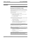
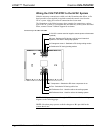
Wiring the CHV-TSTATRF to the HVAC System
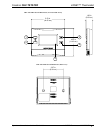
Make the necessary connections as called out in the illustrations that follow. A flat
head screwdriver (not supplied) is required to attach the control wires from the
HVAC system. Apply power after all connections have been made.
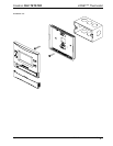
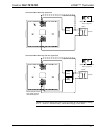
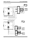
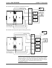
The illustrations on the following pages show examples for connection to various
types of HVAC systems. If your system does not match any of the systems described
below, contact Crestron Technical Support for assistance.
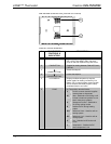
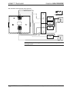
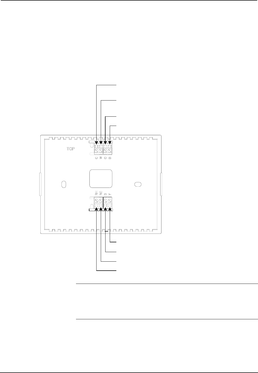
Connections for the CHV-TSTATRF
RH: Reference Heat - Used for calls to the heating system
RC: Reference Cool - Used for calls to the cooling system
G: Fan - Switched to RC during call for fan
Y: Compressor - Switched to RC when compressor is run
C: 24 VAC common terminal supplies remote power to thermostat
(optional)
W: Heat - Switched to RH during a call for heat in heat/cool
systems or aux heat in heat pump systems
O: Changeover control - Switched to RC during cooling modes
B: Switched to RC during heating modes
NOTE: 24 Volt power is returned through the RH connector. Refer to wiring
diagrams on the following pages.
NOTE: Most heat pump systems use O for changeover. B is provided for the
systems that do not.
10 • infiNET™ Thermostat: CHV-TSTATRF Operations & Installation Guide – DOC. 6490