


infiNET™ Thermostat Crestron CHV-TSTATRF
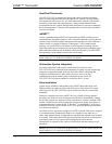
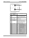
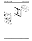
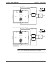
CHV-TSTATRF (Connection View, front with cover removed)
6
6
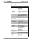
Connectors, Controls & Indicators
# CONNECTORS,
CONTROLS &
INDICATORS
DESCRIPTION
1 MODE BUTTON
Cycles through available System Modes:
OFF, HEAT, AUX HEAT ONLY (for heat
pump or dual-fuel systems only) and COOL.
2 FAN BUTTON
Toggles fan setting between FAN AUTO and
FAN ON.
3
(RAISE BUTTON)
Raises the setpoint.
4
(LOWER BUTTON)
Lowers the setpoint.
5 LCD DISPLAY
Displays ambient temperature, setpoint,
system mode, fan setting, call activity, low
battery, RF or control system communication
errors, firmware download progress, setup
parameter/function and value.
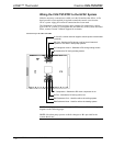
6 HVAC (4) Two-position terminal blocks.
C 24 VAC common terminal supplies
remote power to thermostat
W Heat – Switched to RH during a call
for heat in heat/cool systems or aux
heat in heat pump systems
O Changeover control – Switched to
RC during cooling modes
B Switched to RC during heating
modes
RH Reference Heat – Used for calls to
heating system
RC Reference Cool – Used for calls to
cooling system
G Fan – Switched to RC during call
for fan
Y Compressor: - Switched to RC
when compressor is run
6 • infiNET™ Thermostat: CHV-TSTATRF Operations & Installation Guide – DOC. 6490