


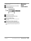
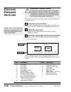


The pressure switch is a non-adjustable switch. To check the
pressure switch:
Locate the pressure switch.
Use the wiring diagrams that came with your chiller for
exact location. Location varies depending on size of unit.
Check the connections.
Make sure all connections to the switch are secure.
Tighten as needed.
Check the control signal in the electrical panel.
Refer to the wiring diagram and the following table for
the switch status:
Series 1 Portable Chillers, TIC Control UGH016/0500
6-22
TROUBLESHOOTING
C
HECKING
PRESSURE
SWITCHES
WARNING: Coolant hazard
Coolant can cause freezing of skin. All proper
precautions should be taken any time the cool-
ing system is worked on. Any adjustment that
involves the coolant should only be performed
by a certified refrigeration technician.
1
2
3
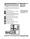
Always refer to the wiring dia-
grams you received with your
chiller to locate specific elec-
trical components.
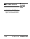
Input
1
2
3
4
5
6
7
8
9
10
11
12
I 123456789 101112
O12345678
DAY
TIME
Description
Chiller Stop
Chiller Start
Level Switch
Flow Switch
Compressor Running
Pump Running
Suction Pressure Switch
Discharge Pressure Switch
Low Temperature Deviation
Optional Auto-Fill Level Switch
Pressure Differential Switch
(7.5, 10, 15 ton only)
Optional Alarm Silence
Output
1
2
3
4
5
6
7
8
Description
Compressor Starter
Compressor Run Lamp
Pump Starter
Pump Run Lamp
Alarm Lamp
Optional Auto-Fill Solenoid
Optional Alarm Bell
Optional Alarm Strobe
In this example, inputs 7 and 8 are highlighted; they are in
normal position. If they are not highlighted the input is out of
range.
Inputs
Outputs