


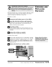

CHECKING AND
REPLACING
SWITCHES
UGH016/0500 Series 1 Portable Chillers, TIC Control
TROUBLESHOOTING 6-15
Always refer to the wiring
diagrams that came with
your chiller to locate specific
electrical components.
WARNING: Electrical hazard
Before performing any work on this unit, discon-
nect and lock out electrical power sources to
prevent injury from unexpected energization or
startup.
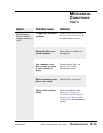
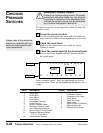
The pump tank has one or two float switches. The float switch
(low level cutout) activates an alarm. There is also a flow
switch in the process fluid line to verify flow.
To replace a switch:
Disconnect and lockout power to the chiller.
Open the electrical enclosure and locate the
connection for the correct switch on the terminal switch.
Refer to the wiring diagrams you received with your
chiller to find the correct terminals.
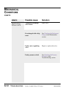
Check the switch.
Check continuity within the switch and make sure it cor-
responds to the condition of the switch. Clean the switch
if needed.
Replace the switches as needed.
Drain the tank to replace the switch(es).
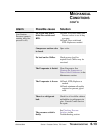
To check a flow switch:
Remove the electrical cover on the flow switch.
Slide the top of the switch housing over until
the N.O. (normally open) shows when electrical cover is
placed back on.
Replace electrical cover on flow switch.
1
2
3
4
1
2
3
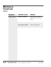
Flow switch
Level switch