


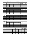
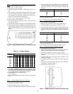
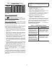

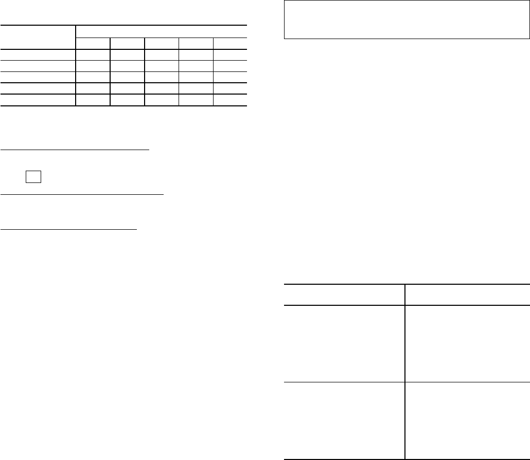
Table 27 — Terminal Strip J5 Connector
Resistance Reading
QUICK TEST
STEP NO.
J5 PIN NUMBERS
12345
1. to 2.5. ϱϱϱϱ0
2.6 00ϱϱ0
2.7. 0 ϱ 0 ϱ 0
2.8. 0 ϱϱ00
2.9. to 3.3. 0 ϱϱϱ0
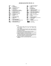
LEGEND
ϱ — Infinity
Step 2 — Check the Display LEDs
1. Enter Quick Test mode.
88
2. If is not displayed, replace display board.
Step 3 — Check Set Point Potentiometer — Advance the dis-
play to quick test step 1.9. to determine if this potentiometer
is set and connected properly.
Step 4 — Check Display Switch — Press switch. If switch
does not click, it is faulty and the display will be energized
continuously. The switch is an integral part of display board
and cannot be replaced separately.
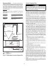
ACCESSORY BOARD CHECKOUT— The accessory board
can be completely checked using quick test steps 2.0., 2.2.,
and 2.3. It can also be checked out as follows:
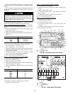
1. Remove the accessory board connector from the proces-
sor board and connect an ohmmeter to terminals 3 and 4
on the connector. Numbers are marked on the connector.
See Fig. 15.
2. Set the meter to 10,000 ohms. The resistance value ob-
tained should be 3,333 ohms. Adjust the potentiometers
and the resistance value should not change.
3. Connect the ohmmeter to terminals 3 and 6. As the reset
limit potentiometer is turned clockwise, resistance should
increase from 0 to approximately 3,400 ohms.
4. Connect the ohmmeter to terminals 3 and 5.As the econo-
mizer minimum position potentiometer is turned clock-
wise, resistance should increase from 0 to approximately
3,400 ohms.
5. Connect the ohmmeterto terminals 3 and 2.As the warm-up
set point potentiometeris turned clockwise, resistance should
increase from 0 to approximately 3,400 ohms.
If any of the Steps 1 through 5 result in any other ohm
reading, replace the board; it cannot be serviced.
TWO-STEP DEMAND LIMIT CONTROL MODULE
(DLCM) TROUBLESHOOTING — If a problem is
suspected in the DLCM board, use the following test
procedure:
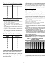
The board can only be checked when it is connected to
the processor and the processor is energized so that the DLCM
is supplied with 5 vdc power. The terminals referenced are
shown in Fig. 16. Potentiometers P1 and P2 refer to the DLCM
potentiometers.
IMPORTANT: Be careful to avoid damaging the con-
nector or the processor board when taking the voltage
readings.
Test under the following conditions:
• No power to IN1 or IN2
Terminal 1 to 2 should read 4.5 vdc ±0.1 v
Terminal 2 to 3 should read 5.0 vdc ±0.1 v
• Power to IN2 or to both IN1 and IN2, and P2 set at 24%
Terminal 1 to 2 should read 1.5 vdc ± 0.1 v
NOTE: Voltage should vary between 0.5 vdc and 2.5 vdc
as the setting of P2 is varied between 0% and 49%.
Terminal 2 to 3 should read 5.0 vdc ± 0.1 v
• Power to IN1 only and P1 set at 50%
Terminal 1 to 2 should read 2.5 vdc ± 0.1 v
Terminal 2 to 3 should read 5.0 vdc ± 0.1 v
NOTE: Voltage should vary between 0.5 vdc and 2.5 vdc
as the setting of P2 is varied between 50% and 100%.
NOTE: If the voltages listed in these 3 tests are not obtained
during testing, the DLCM board must be replaced.
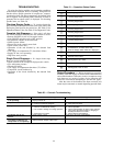
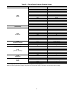
Enthalpy Sensor Checkout — To test operation of
enthalpy sensor, see Table 28.
Table 28 — Enthalpy Sensor Checkout
TEST EXPECTED RESULT
AND RESPONSE
Outdoor-air sensor:
Enthalpy sensor + terminal
should be connected to +
terminal on motor. Connect the
positive terminal of a DC
milliammeter to the S terminal
of the sensor and the negative
terminal of the meter to S
O
terminal of the enthalpy board.
Milliammeter reading should be
between 3 and 24 mA if sensor
is operating correctly. If reading
is 0 mA, the sensor is either
wired backwards or is defective.
Indoor-air sensor:
Enthalpy sensor + terminal
should be connected to +
terminal on motor. Connect the
positive terminal of a DC
milliammeter to the S terminal
of the sensor and the negative
terminal of the meter to S
R
terminal of the enthalpy board.
Milliammeter reading should be
between 3 and 24 mA if sensor
is operating correctly. If reading
is 0 mA, the sensor is either
wired backwards or is defective.
51