


DIP SWITCH NO. 1 — Supply Air Set Point (SASP) Reset
Type. Factory setting is OFF. Do not change.
DIP SWITCH NO. 2 — SASP Reset Enabled. Factory set-
ting is OFF (no SASPreset enabled). If SASP reset has been
installed, enable it by changing switch position to ON.
DIP SWITCH NO. 3 — Economizer option. If economizer
option has been installed, this switch will be ON. If there is
no economizer installed, this switch will be OFF. Confirm
setting per Table 10. Change only if in error.
DIP SWITCH NO. 4 — Morning Warm-Up. For 48FK,JK
models, this switch will be ON (morning warm-up enabled).
For 50FK,JK units with factory-installed electric heaters, this
switch will be ON. For all other units, this switch will be
OFF. If accessory electric heaters are installed (for 50FK,JK
without plenum option), change this switch to ON.
DIP SWITCH NO. 5 — Demand Limit. Factory setting is
OFF (demand limit not enabled). If Demand Limit (single-
step or 2-step accessory) has been installed, change this switch
to ON.
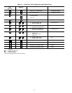
DIP SWITCHES NO. 6 AND NO. 7 — Unloader Configu-
ration. These are factory set to match unit size. Confirm set-
tings per Table 12. Change only if in error.
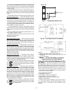
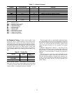
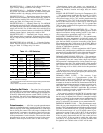
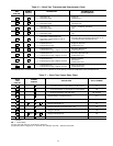
Table 12 — DIP Switches
SWITCH
NO.
FUNCTION
SWITCH
POSITION*
MEANING
1
Reset
Mode
Off
Space or Outdoor-Air Reset
(DO NOT CHANGE)
2
Reset
Select
On
Off
Reset Used
Reset Not Used
3 Economizer
On
Off
Enable Economizer
Disable Economizer†
4
Morning
Warm-Up
On
Off
Enable Morning Warm-Up**
Disable Morning Warm-Up**
5
Demand
Limit
On
Off
Enable Demand Limit
Disable Demand Limit
6,7 Unloaders
Off, Off
On, Off
Off, On
No Unloaders
1 Unloader
2 Unloaders
8 Not Used Off No Significance
LEGEND
DIP — Dual, In-Line Package
*ControlcircuitbreakermustbeoffbeforechangingthesettingoftheDIPswitch.
†No economizer.
**And/or electric heat (50FK,JK units without plenum only).
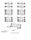
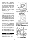
Adjusting Set Points — Set points for unit operation
are established via potentiometer settings. Set points for Sup-
ply Fan controls are set at the VFD keypad (if installed) or
at the IGV differential pressure switch (DPS1) (if IGV op-
tion installed). Set points for modulating power exhaust (op-
tion or accessory) are set at the differential pressure switch
(DPS2).
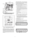
Potentiometers — All of the set point potentiometers
must be set before the unit is started in order for the unit to
function properly. Each of the potentiometers has a valid range
that is used by the control. The valid range is defined as the
potentiometer’s resistance value that the control will not con-
sider to be in error. This is usually between 10% and 90%
of the potentiometer’s total resistance. The control has been
programmed to accept an operational range for the poten-
tiometer, which may not be the same as the valid range.
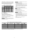
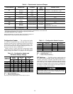
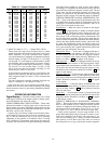
Potentiometer inputs and ranges are summarized in
Table 9. Information on individual set point potentiometers
(including function, location and range data) are shown
below:
SUPPLY AIR SET POINT (Leaving-Air Temperature) (P1)
— This potentiometer establishes the set point for cooling
cycle operation of the VAV unit. The VAV control uses a
valid control range of 45 to 70 F, and the potentiometer has
a valid range of −22 to 70 F. If the set point is between −22
and 45 F, the control will use a value of 45 F. If the set point
is outside the valid range (less than −22 F or greater than
70 F), an alarm condition will be signaled and a default value
of 70 F will be used.
ECONOMIZER MINIMUM POSITION (P5) — This po-
tentiometer specifies the minimum opening position for the
optional economizer during running periods. It has both a
valid range and an operational range of 0 to 100%.
SASP RESET TEMPERATURE (P7) — This potentiometer
establishes the space temperature at which the control will
initiate the reset of the SASP (i.e., the unit control begins to
raise the base SASP, to prevent overcooling of the space).
The potentiometer has a valid range of 40 to 100 F. Refer to
Space Temperature Reset section on page 16 for further dis-
cussion of SASP Reset operation.
RESET LIMIT (P3) — Used in conjunction with P7 poten-
tiometer, this potentiometer establishes the maximum tem-
perature for the modified SASP value during the Reset func-
tion. This potentiometer has a valid range of 0° to 80 F.
DEMAND LIMIT, SINGLE-STEP (P4) — This potentiom-
eter establishes the maximum amount of compressor capac-
ity permitted by the unit control when single-step demand
limit operation is implemented (by closing contact set to po-
tentiometer wiper arm). This potentiometer is field-supplied
and -installed and will be located in the main control box.
The valid range is 0% to 100%, which is also the operational
range.
If the wiper arm is open, all capacity stages can be used.
When the wiper arm is closed, the capacity is reduced by the
amount set on potentiometer P4.
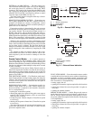
DEMAND LIMIT, 2-STEP — The accessory 2-step
demand limit control is a 2-potentiometer system. The
demand limit control board (DLCM) accessory board is
field-installed in the main control box; the 2 control poten-
tiometers are located on the DLCM. Potentiometer DLCM-P1
establishes the maximum amount of compressor capacity avail-
able when SW1 is closed and has a valid range is 50% to
100%. Potentiometer DLCM-P2 establishes the maximum
amount of compressor capacity available when SW2 is closed
and has a valid range is 0% to 49%.
If no power is supplied to the DLCM, all capacity stages
can be used. When power is supplied to terminal IN1 only,
the first step of demand limit control is energized and the
capacity is reduced by the amount set on potentiometer P1.
When power is supplied to IN2 (or IN1 and IN2), the ca-
pacity is reduced by the amount set on potentiometer P2.
MORNING WARM-UP (P6) — This potentiometer estab-
lishes the set point temperature for the Morning Warm-Up
function. Thisis the temperature at which the morning warm-up
sequence is terminated and VAV cooling operation begins.
The valid control range is 0° to 95 F, but the control is pro-
grammed to accept a range of 40 to 80 F. If the set point is
between 0° and 40 F, the control will use a value of 40 F.
If the set point is between 80 and 95 F, the control will use
a value of 80 F. If the set point is outside the valid range
(less than 0° F or greater than 95 F, an alarm condition will
be signaled and a default value of 40 F will be used.
27