


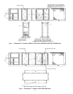
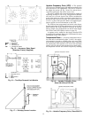
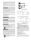
Variable Frequency Drive (VFD) — The optional
VFD is used to modulate supply fan airflow to maintain duct
static pressure on VAV applications. The VFD is located in
the supply fan section (see Fig. 18 and 19), and can be ac-
cessed by opening the fan section access door.
The unit is supplied with a pressure transducer capable of
measuring from 0.0 to 5.0 in. wg. The pressure transducer
will senda4to20mAsignal to the VFD to modulate the
speed of the indoor fan motor to precisely control the fan to
the desired static pressure set point. The VFD is factory set
at 2.5 in. wg duct static pressure. Refer to the Operating Se-
quence section for more information on the VFD.
The VFD has been programmed and wired at the factory
for this application. No further adjustments (except for Duct
Static Pressure Set Point) should be necessary at start-up.
Factory jumper wire configurations are shown in the Supply
Fan Control with VFD Option section on page 28.
A separate service manual for the factory-installed VFD
is supplied with each unit. Refer to the VFD manual for more
information on the VFD controls.
Temperature Reset — Accessory temperature reset al-
lows the unit to automatically adjust (‘‘reset’’) the supply-
air temperature set point to a higher value once most of the
space cooling load has been met. When the space conditions
are satisfied, the VAV terminals will close to the minimum
position.AllVAV units willsense the decrease in actual supply-
air temperature and the unit controls respond by reducing
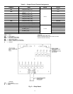
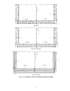
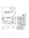
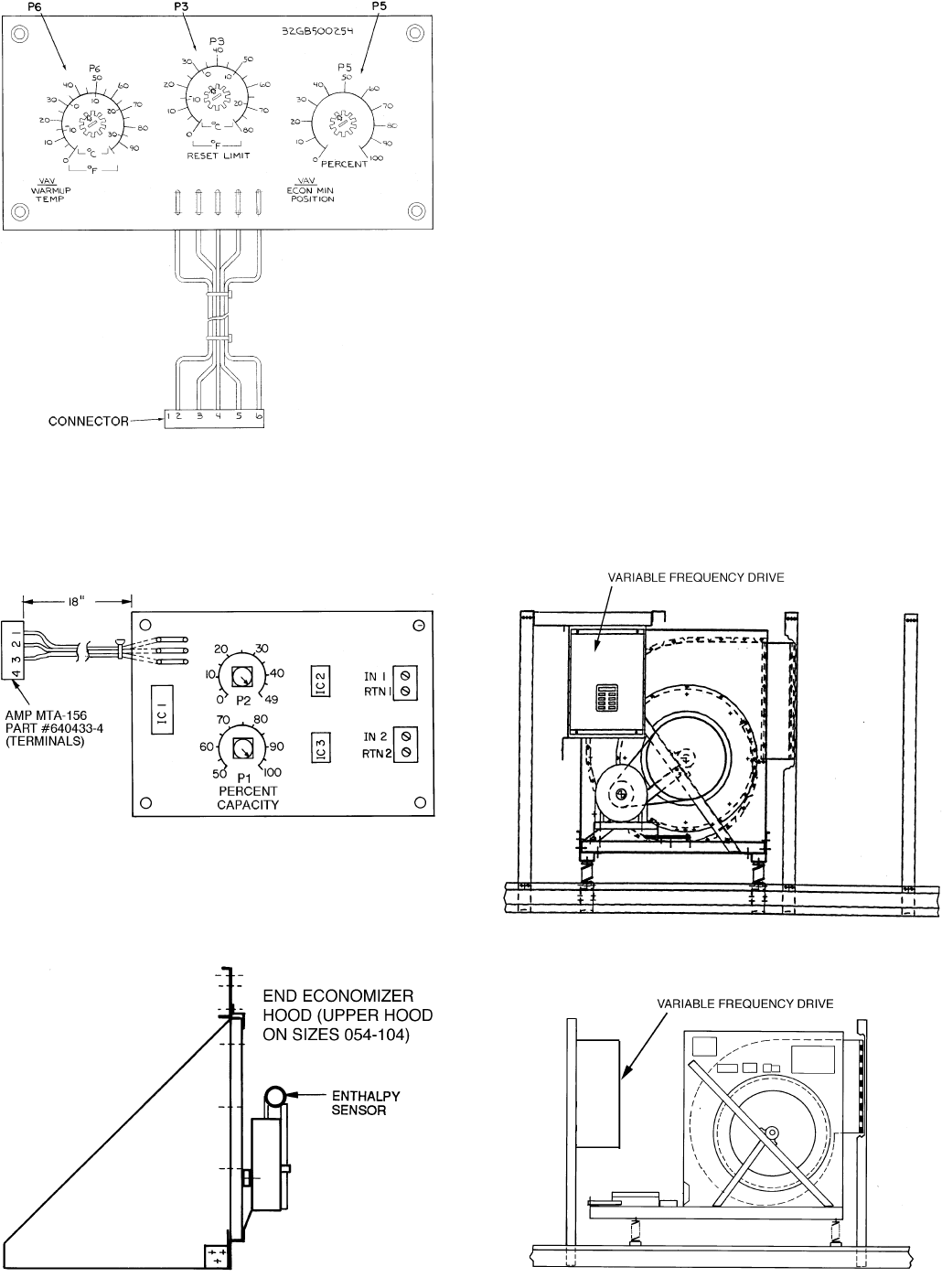
LEGEND
ECON — Economizer
MIN — Minimum
P—Potentiometer
VAV — Variable-Air Volume
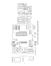
Fig. 15 — Accessory Relay Board
(Standard; Factory Supplied)
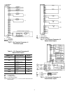
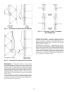
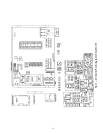
LEGEND
IC — Integrated Circuit
IN — Input
P—Potentiometer
RTN — Return
Fig. 16 — Two-Step Demand Limit Module
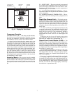
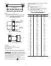
Fig. 17 — Enthalpy Sensor Location
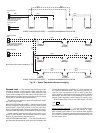
Fig. 18 — Variable Frequency Drive,
Sizes 034-048 and 078-104
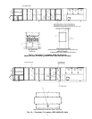
Fig. 19 — Variable Frequency Drive, Sizes 054-074
12