


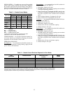
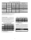
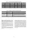
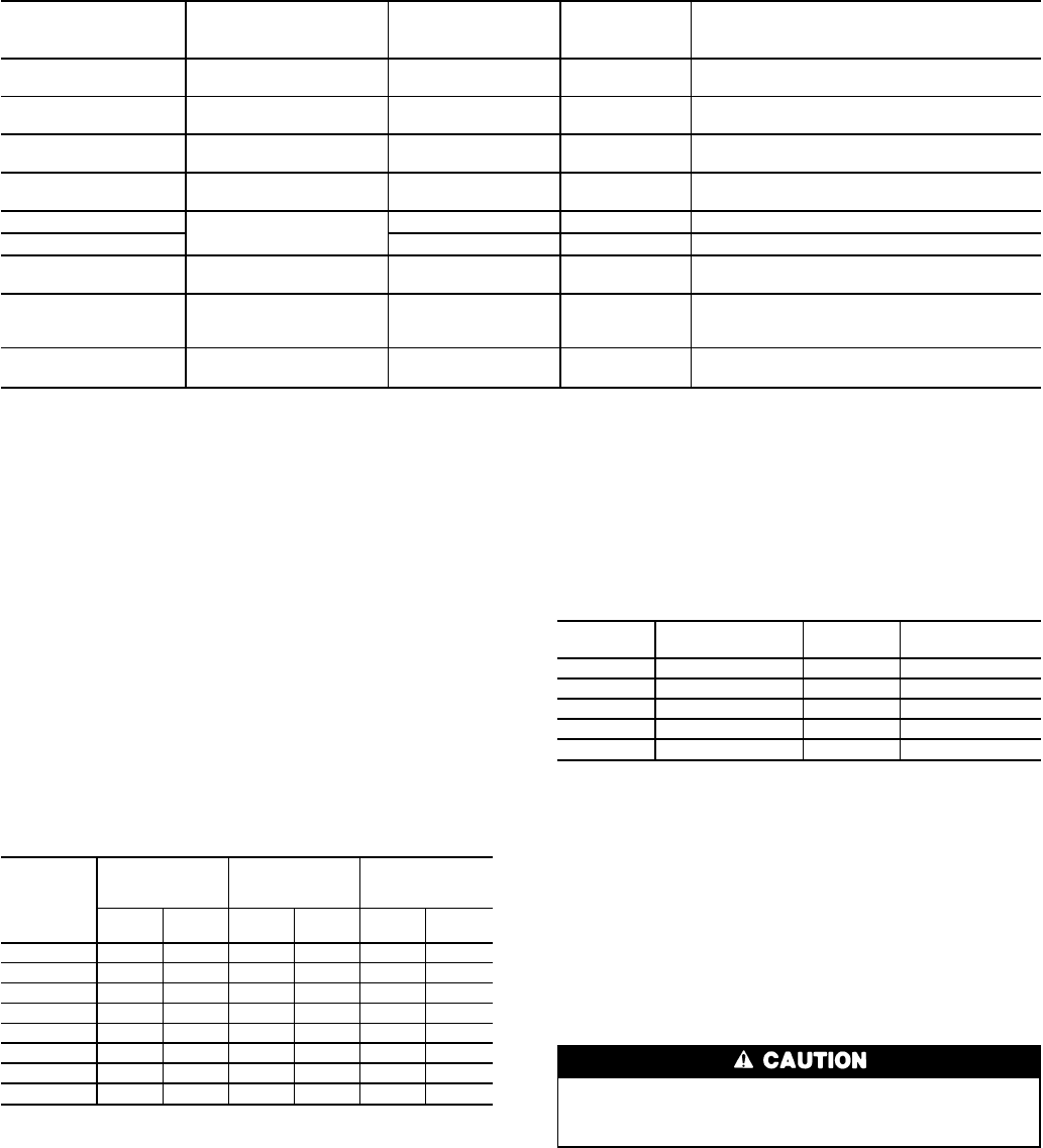
Table 9 — Potentiometer Inputs and Ranges
POTENTIOMETER DESCRIPTION LOCATION
CONTROL
VALID
RANGE
DEFAULT VALUE
P1
Supply Air
Set Point
Display
Board
45 to 70 F
45Fif-22F<P1<45F
70FifP1>70FORIFP1<-22F
P2*
Economizer
Position
Economizer
Motor
0 to 100% None (0 if P2 is bad)
P3 Reset Limit
Accessory
Board
0 to 80 F None (limited to 70 F maximum)
P4†
Demand Limit,
Single-Step
Main Control Box 0 to 100% None
DLCM-P1
Demand Limit,
2-Step
DLCM Board 50 to 100% None
DLCM-P2 DLCM Board 0 to 49% None
P5*
Minimum Economizer
Position
Accessory Board 0 to 100% None
P6
Warm-Up
Set Point
Accessory Board 40 to 80 F
40Fif0°F<P6<40FORIFP6<95F
OR IF P6 < 0
80Fif80F<P6<95F
P7**
Reset
Temperature
Reset Board 40 to 100 F None
*Optional factory-installed economizer is required. Potentiometer P2 is not a set point.
†Accessory two-step demandlimit module is required(which has 2 potentiometers),ora5to20k-ohm
field-supplied potentiometer is required for single-step demand limit.
**Accessory temperature reset is required.
NOTE: Potentiometers P1-P6 input data to pin terminal connector J3.
Potentiometer P7 inputs data to pin terminal connector J1.
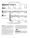
Configuration Header — The configuration header
is a series of 8 small wires that are broken (open circuit) or
unbroken (closed circuit) in a pattern to indicate several unique
characteristics of the unit. The configuration header is fac-
tory set and should not be changed; changing the factory set-
ting may cause the unit to malfunction.
Before start-up, visually check the configuration header
against the factory setting for the unit size. See Table 10 for
factory settings. See Table 11 for purpose for each jumper.
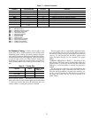
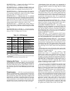
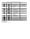
Table 10 — Configuration Header and
DIP Switch Factory Settings
JUMPER OR
SWITCH NO.
UNIT SIZES
034-038,
048-088
UNIT SIZE
044
UNIT SIZE
104
Header
Position
Switch
Position
Header
Position
Switch
Position
Header
Position
Switch
Position
1 ▫ Off ▫ Off ▫ Off
2 Ⅲ Off Ⅲ Off Ⅲ Off
3 Ⅲ On/Off* Ⅲ On/Off* Ⅲ On/Off*
4 ▫ On/Off* ▫ On/Off* Ⅲ On/Off*
5 ▫ Off ▫ Off ▫ Off
6 Ⅲ Off Ⅲ On Ⅲ On
7 ▫ On ▫ Off ▫ Off
8 Ⅲ Off Ⅲ Off Ⅲ Off
LEGEND
DIP — Dual, In-Line Package
▫ — Broken Jumper (open circuit)
Ⅲ — Unbroken Jumper (closed circuit)
*Depending on factory-installed options or field-installed accessories.
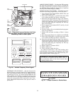
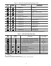
Table 11 — Configuration Header Jumpers
JUMPER
NUMBER
FUNCTION
FACTORY
SETTING
MEANING
1,2 Unit Type ▫Ⅲ VAV Rooftop Unit
3,4,5 Qty Compressors Ⅲ▫▫ 2 Compressors
6 Expansion Valve Ⅲ TXV
7 Power Frequency ▫ 60 Hz
8 Not Used Ⅲ No Significance
LEGEND
TXV — Thermostatic Expansion Valve
VAV — Variable-Air Volume
▫ — Broken Jumper (open circuit)
Ⅲ — Unbroken Jumper (closed circuit)
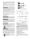
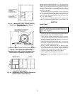
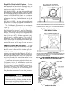
DIP Switches — The DIP switches configure the unit
for several factory-installed options and field-installed ac-
cessories, plus factory unloaders. The DIP switches are lo-
cated under a plastic enclosure which must be removed for
access. See Fig. 1. The switches can be field adjusted. Switches
must only be adjusted when control power is deenergized.
See Table 12 for DIP switch purposes and Table 10 for fac-
tory settings of the switch positions.
Disconnect control power before changing the settings
of the DIP switches. To disconnect control power, open
the control circuit breaker.
26