


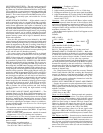

OCCUPIED/UNOCCUPIED — The unit control system will
initiate normal occupied mode functions (including Morn-
ing Warm-up, Economizer Minimum Position, and Cooling
Cycle) whenever a contact closure is made that emulates the
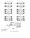
normal timeclock contacts.See Fig. 23. (‘‘Occupied/Unoccupied
Switch’’). The contact closure from the BMS must be an iso-
lated contact set, normally open, and suitable for 24-volts
AC pilot duty.
NIGHT SETBACK CONTROL — Night setback control is
used to control the space to a set point level that is typically
lower than during normal occupied periods (Heating Only
mode). Some applications also require a limitation on the
maximum space temperature during unoccupied periods (Cool-
ing mode). Both modes are possible by closing the same con-
tacts used in the Occupied/Unoccupied control, or by installing
a dedicated contact set in parallel with the Occupied/
Unoccupied control contacts, and using the BMS space tem-
perature sensing system and its logic to determine when to
initiate unit operation.
Once the unit operation has been initiated by the BMS
contact closure, the unit operates in its normal occupied mode
manner, initiating morning warm-up if needed (as sensed by
return air temperature to the unit) or cooling (controlling to
current SASP value). The Night Setback Control contacts
will interrupt normal unit operation when the BMS senses
that space temperatures have returned to unoccupied set point
levels, and the unit will shutdown normally.
The contact closure from the BMS must be an isolated
contact set, normally open, suitable for 24-voltsAC pilot duty.
NOTE: If the rooftop unit is equipped with a VFD and night
setback cooling operation is intended, the fan system must
be controlled to permit FULL SUPPLY FAN AIR DELIV-
ERY during unoccupied cooling operation. This is most con-
veniently attained by replicating the HIR relay function of
the rooftop unit. An HIR control sequence will force all room
terminals to their minimum heating CFM position, thus as-
suring adequate airflow through the rooftop unit during night
setback cooling operation. During night setback cooling op-
eration, the return-air temperature (RAT) will be well above
normal levels. The higher RAT means that the air tempera-
ture leaving the evaporator coil will also be well above nor-
mal levels. This situation is interpreted by the unit control
system as a demand for additional cooling stages. The unit
control responds to this demand by bringing on more stages,
until typically all stages are active. If the VFD is not work-
ing in-step with the refrigeration system demand, it is pos-
sible to produce low suction pressures and local frosting
on the evaporator coil during the night setback cooling
operation.
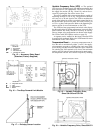
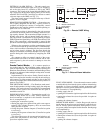
UNIT SUPPLY AIR SET POINT ADJUSTMENT — The
minimum Supply Air Set Point (SASP) temperature is es-
tablished by the setting at Potentiometer P1 on the unit dis-
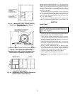
play board (see Fig. 6). The control point can also be adjusted
upward by emulating the function of the accessory Space
Temperature Reset package. The BMS can be used to cause
this reset by adjusting the resistance value in a variable re-
sistance transducer witha4to20mAor2to10vdcsignal
generated by the BMS.
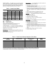
This emulation requires the following field-supplied parts:
• Variable resistance transducer (Kele RES-1 or equivalent,
range 0 to 1000 ohms)
• Series resistance with potentiometer, suitable for manual
adjustment to 12.5 to 13.0 k-ohms total resistance
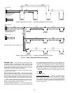
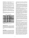
Field Connections (see Fig. 30) — Connect fixed resistance
with manual potentiometer and variable resistance trans-
ducer in series.
Connect wiring to rooftop unit at:
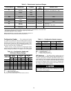
Size 034-044: TB3-12 and TB3-15
Size 054-104: TB4-12 and TB4-15
Configuration — Configure as follows:
1. Set DIP switch no. 2 to ON.
2. Adjust manual potentiometer to 12.6 to 12.8 k-ohm.
3. Configure transducer for job site input signal from BMS.
4. Adjust Potentiometer (P3) on the rooftop to MAXIMUM
SASPvalue (typically 65 to 70 F).The maximum P3 SASP
control limit is 70 F.
Operation —Unit will initiate SASP Reset (adjust config-
ured SASP upward) when the sum of the resistance (fixed
resistance+potentiometer+ transducer)exceeds 13.1k-ohm.
Once reset is initiated, full range of reset (P3 setting minus
configured SASP) will be reached with 500-ohm increase in
transducer resistance (TR).
During Reset mode operation, Code 21 will appear on unit
display board.
Formula:
MSP = SASP +
[]
(P3 − SASP) (0.6 F)
x x (TR − R@13.1)
(3) (100 ohm)
MSP: Modified SASP (SASP plus Reset)
TR: Resistance at transducer
R@13.1: TR required to reach 13.1 k-ohm start level
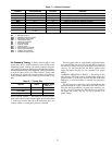
DEMAND LIMIT (1-STAGE OR 2-STAGE) — Both of the
Demand Limit functions on the units rely on external switches
to initiate the reset functions. Contact closures by the BMS
can be used in place of these switches. Contacts must be
isolated and suitable for 115-vac pilot duty operation.
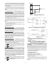
For Single-Step Demand Limit, emulate function of switch
SW with contact closure controlled by the BMS. Set poten-
tiometer P4 manually at the unit control box. Alternatively,
potentiometer P4 might also be emulated by a variable re-
sistance transducer, with the BMS now able to adjust the
amount of demand limit.
For 2-Step Demand Limit, install the accessory Demand
Limit Control Module (DLCM) according the instructions
on page 18. Replace switch functions Switch 1 and Switch
2 with contact closures controlled by the BMS (see Fig. 29).
Follow unit control configuration instructions in the De-
mand Limit section on page 18.
SUPPLY DUCT PRESSURE SET POINT ADJUSTMENT
— Supply duct pressure set point adjustment from a remote
BMS is possible when the unit has been equipped with a
factory-option VFD (variable frequency drive). There are two
methods available:
• Direct 4 to 20 mA signal
• DDC direct to the VFD
Direct 4 to 20 mA Signal — During normal unit operation,
the factory-installed VFD receivesa4to20mAsignal from
the Duct Pressure (DP) transducer which indicates current
supply duct pressure. The VFD then determines the appro-
priate fan speed (using its internal PID logic feature) and
adjusts its output to the supply fan motor to suit. It is pos-
sible to emulate this 4 to 20 mA control signal by the BMS,
which will transfer control of the VFD to the BMS.
NOTE: When providing a direct 4 to 20 mA signal to the
VFD from a BMS with DP logic, disable the PID (propor-
tion integrated derivative calculation process) feature of the
VFD.
DDC Direct to the VFD — Several accessory interface boards
are available for the VFDs that permit direct communication
between the VFD and several BMS communication sys-
tems. Contact your Carrier representative for information on
selecting an appropriate accessory interface board and the
name of the local service office (for sale and installation of
the accessory boards).
20