


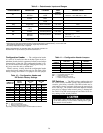
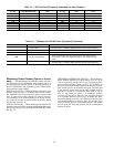
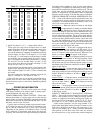
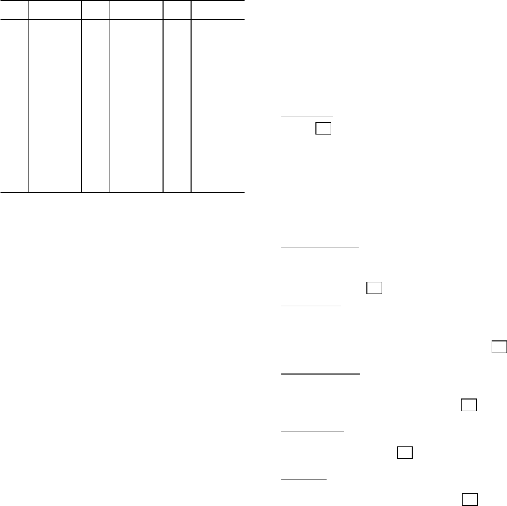
Table 18 — Sensor Resistance Values
TEMP
(F)
RESISTANCE
(Ohms)
TEMP
(F)
RESISTANCE
(Ohms)
TEMP
(F)
RESISTANCE
(Ohms)
−60 362,640 45 11,396 150 1,020
−55 297,140 50 9,950 155 929
−50 245,245 55 8,709 160 844
−45 202,841 60 7,642 165 768
−40 168,250 65 6,749 170 699
−35 139,960 70 5,944 175 640
−30 116,820 75 5,249 180 585
−25 98,420 80 4,644 185 535
−20 82,665 85 4,134 190 490
−15 69,685 90 3,671 195 449
−10 58,915 95 3,265 200 414
−5 50,284 100 2,913 205 380
0 42,765 105 2,600 210 350
5 36,475 110 2,336 215 323
10 31,216 115 2,092 220 299
15 26,786 120 1,879 225 276
20 23,164 125 1,689 230 255
25 19,978 130 1,527 235 236
30 17,276 135 1,377 240 219
35 14,980 140 1,244
40 13,085 145 1,126
3. Quick Test Steps 2.4.-3.3. — Output Relay Check
These quick test steps allow microprocessor to check
output signals fromrelay boards in unit controlsystem. In ad-
dition, operation of all the condenser fans, compres-
sors, and economizer (if equipped) are checked at each step.
Normal display for Steps 2.4. through 2.8. is 1. In Steps
2.9. through 3.2., each compressor and unloader is started
and allowed to run for approximately 10 seconds.At start-
up, a 0 will appear on the display followed by a 1 (Steps
2.9. and 3.2.) in a few seconds. Steps 3.0. and 3.1. will
always be 0 since there are unloaders, and Step 3.3. will
always be zero since it is not used.
At end of the 10-second time period, a 0 will return to the
display board indicating that test step has been success-
fully completed (Steps 2.9. and 3.2.). The 1 indicates that
was tested.
Fan and compressor operating sequence for quick test
Steps 2.4. through 3.3. are shown in Table 17.
If the quick test steps do not operate as described above,
a defect exists in one or more of the following: relay being
tested, electronic control, or unit wiring. Determine problem
and correct.
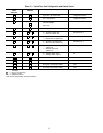
OPERATING INFORMATION
Digital Display —
The VAV control system uses a 2-digit
LED display located on the display board to display opera-
tional information and diagnostic codes.
CODES 0 THROUGH 8, CAPACITYSTEPS — These codes
indicate the number of cooling stages active at the time the
display button is pressed. The highest code indicated on the
display will be 6 for the 034,038 and 048-088 units, 4 for the
044 units, and 8 for the 104 units.
Capacity steps are directly related to pin terminal connec-
tor J6 output. At step zero, the unit has no mechanical cool-
ing on, and the economizer may or may not be operating
(depending on the outdoor air conditions). Once a cooling
load is detected (T1 thermistor reads above the supply-air
set point), the economizer will begin modulating to meet the
load if the outdoor enthalpy is good. As long as the outdoor-
air enthalpy is acceptable, no mechanical cooling will take
place until the economizer dampers are fully open. The rest
of the steps and the operational sequence vary due to the
number of compressors and unloaders. Refer to Operating
Sequence section on page 35 for the unit stages of operation.
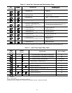
CODES 20 THROUGH 30AND 88, OPERATIONAL STA-
TUS — These codes indicate special operational modes, such
as initialization, morning warm-up, temperature reset, de-
mand limit, or an internal failure of the board. Codes 23-25
and 27-29 are not used on these units.
Initialization — When the control is turned on, the display
20
shows a for approximately 2 minutes to indicate that the
control is in the initialization mode. During this time, the
economizer dampers open and close to determine the resis-
tance range of the economizer position potentiometer (P2)
for full economizer operation. The processor loads the nec-
essary constants for proper unit operation and checks the ther-
mistors and other potentiometers for their values and valid-
ity. After the initialization period, the display screen goes
blank until the display button is pressed. If the display but-
ton is pressed during the 2-minute initialization period, the
control goes into the Quick Test mode.
Temperature Reset — If the unit is equipped with the ac-
cessory temperature reset package, and DIP switch 2 is in
the ON position, the unit will reset the supply-air tempera-
ture to a calculated value when necessary. When this con-
21
dition is in effect, a will appear in the display.
Demand Limit — If the unit is equipped with the accessory
demand limit control module or the field-supplied, single-
step demand limit potentiometer, and DIP switch 5 is in the
ON position, the unit will limit the capacity stages to a pre-
22
determined value. When this condition is in effect, a will
appear in the display.
Morning Warm-Up —If the morning warm-up heat routine
is enabled using DIP switch 4, and conditions of the occu-
pied space warrant, the unit will begin the morning warm-up
26
routine. When this condition is in effect, a will appear
in the display.
Internal Failure — If the unit detects an internal fault (such
as a time measurement failure), or detects an incorrect volt-
30
age on an input channel, a will be displayed, and the
unit will shut down.
Quick Test — If the display button is pressed during the
initialization period of the processor, the unit will run its self-
88
diagnostic routine. When this is in effect, an will appear
in the display screen.
CODES 51 THROUGH 87, DIAGNOSTIC INFORMA-
TION — These codes indicate diagnostic information when
there is a unit problem such as a faulty thermistor, potenti-
ometer, or compressor fault. Refer to Diagnostic Codes sec-
tion on page 45 for more details. Codes 53, 54, 57, 58, 61,
62, 65-69, 73, 74, and 77-80 are not used on these units.
Under normal operation, only the stage number is dis-
played when the display button is pressed. If a status or over-
load code is displayed, the display will rotate every 2 sec-
onds and will display up to 3 codes. Overload information
takes priority over all other codes. The codes are stored in
the microprocessor as long as the board remains energized.
34