


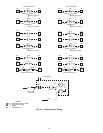
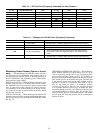
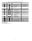
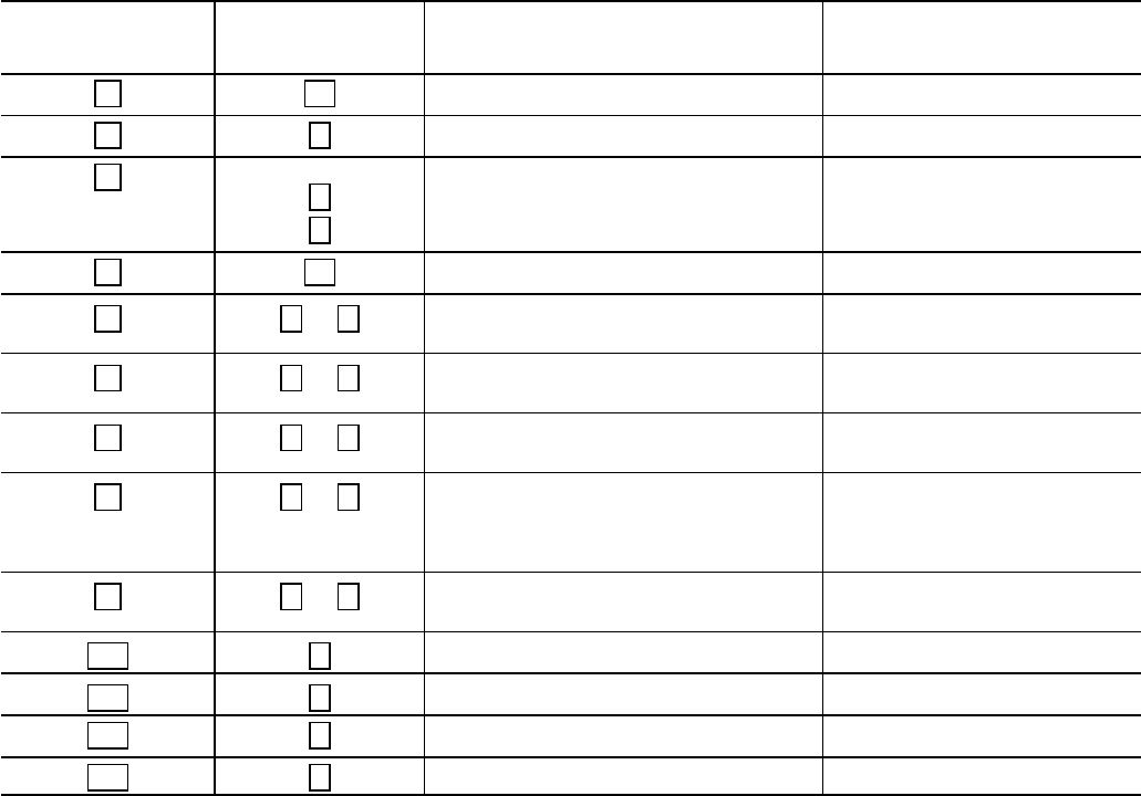
Table 15 — Quick Test, Unit Configuration and Switch Check
QUICK
TEST
STEP NO.
NORMAL
DISPLAY
DESCRIPTION CONTROL SWITCH
1.
01
Type Unit — Air-Cooled VAV Configuration Header
2.
2
No. of Compressors Configuration Header
3.
2
1
No. of Unloaders
(034,038,048-088)
(044, 104)
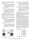
DIP Switch No. 6 and 7
4.
60
60-Hertz Power Configuration Header
5.
0 or 1
0 — No Reset (Switch Off)
1 — Reset On (Switch On)
DIP Switch No. 2
6.
0 or 1
0 — No Economizer (Switch Off)
1 — Economizer On (Switch On)
DIP Switch No. 3
7.
0 or 1
0 — No Warm-Up (Switch Off)
1 — Warm-Up Used (Switch On)
DIP Switch No. 4
8.
0 or 1
0 — Demand Limit Not Used
(Switch Off)
1 — Demand Limit Used
(Switch On)
DIP Switch No. 5
9.
0 or 1
0 — Enthalpy Switch Open
1 — Enthalpy Switch Closed
EC
1.0.
1
1 — Low-Pressure Switch Closed Low-Pressure Switch 1
1.1.
1
1 — Low-Pressure Switch Closed Low-Pressure Switch 2
1.2.
1
No Circuit 1 Oil Pressure Switch None*
1.3.
1
No Circuit 2 Oil Pressure Switch None*
LEGEND
DIP — Dual, In-Line Package
EC — Enthlapy Control
VAV — Variable Air Volume
*Units are not equipped with oil pressure switches.
32