


Incorrect Potentiometer Setting — Apotentiometer turned fully
clockwise or counterclockwise is outside the valid range and
will result in a failure.
Faulty Wiring — If the wiring between the potentiometer and
the processor board is incorrect, a failure will result.
Potentiometer Failure — If potentiometer is shorted or open,
a failure will occur.
CODE 85: DEMAND LIMITPOTENTIOMETER (P4) FAIL-
URE — Used only if demand limit is being used. If demand
limit is used, DIP switch 5 must be in the ON position.
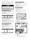
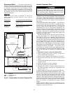
Two types of demand limit are available: a field-supplied
and installed single-step control consisting of a 10 Kohm,
3-wire linear potentiometer and an accessory 2-step control
are available from Carrier. The single-step control has a single
potentiometer while 2-step control has 2 potentiometers
(mounted on the demand limit board, see Fig. 26).
For both types of demand limit, the control uses only 80%
of the total potentiometer resistance. If resistance of poten-
tiometer is less than 10% or greater than 90%, alarm light
85
will be energized, a diagnostic code of will be displayed
when the display button is pushed, and demand limit will be
terminated. If a failure occurs, it is probably due to one of
the following:
Potentiometer Failure — If a potentiometer is shorted or open,
a failure will occur.
Incorrect Potentiometer Setting — Apotentiometer turned fully
clockwise or counterclockwise will put potentiometer out of
range resulting in an error.
Faulty Wiring — If wiring between the potentiometer and
the processor board is incorrect, an error will occur.
DIP Switch 5 — If DIP switch 5 is in the ON position and
potentiometer is not installed, an error will occur.
CODE 86: MINIMUM POSITION ECONOMIZER PO-
TENTIOMETER FAILURE — If potentiometer P5 (on ac-
cessory board) setting is less than 0% or greater than 100%,
86
alarm light will be energized, a code of will be dis-
played when display button is pushed and economizer out-
door air dampers will move to the fully closed position.
The potentiometer full-scale resistance is 10 Kohm, but
when installed in parallel with the other 2 potentiometers on
the accessory board, measured resistance will be 3.3 Kohm.
This failure will automatically reset when potentiometer
returns to normal.
If a failure occurs, one of the following is the probable
cause:
DIP Switch 3 — If this switch is in the ON position and the
accessory board is not installed (accessory board is standard
on these units, so it should always be on the unit).
Incorrect Potentiometer Setting — If potentiometer is turned
fully clockwise or counterclockwise, potentiometer will be
out of the allowable range, and an error will result.
Faulty Wiring — If wiring between the potentiometer and
the processor board is incorrect, an error will occur.
Potentiometer Failure — If potentiometer is shorted or open,
potentiometer will be out of range and an error will result.
CODE 87: WARM-UPTEMPERATURE SETPOINT FAIL-
URE —Applicable only if morning warm-up is used. Whether
or not unit is equipped with electric resistance heaters, use
of the morning warm-up function is recommended if the unit
is shut down at night or over weekends. In this application,
cooling will remain off and the outdoor-air damper will stay
closed until heat load from the occupied space elevates return-
air temperature to the warm-up set point. If warm-up func-
tion is used, DIP switch 4 must be in the ON position. The
potentiometer (P6) is located on the accessory board. If po-
tentiometer is set at less than 0° F or more than 95 F, alarm
87
light will be energized, a diagnostic code of will ap-
pear on the display when display button is pushed, and con-
trol will use a default value of 40 F. If setting is between
0° F and 40 F, control will use a value of 40 F but no di-
agnostic code will be displayed; if setting is between 80 F
and 95 F, control will use a value of 80 F but no diagnostic
code will be displayed.
The potentiometer full-scale resistance is 10 Kohm, but
when wired in parallel with other potentiometers on the ac-
cessory board, measured resistance is 3.3 Kohm.
The failure will automatically reset once potentiometer re-
turns to normal. If a failure occurs, one of the following is
the probable cause:
DIP Switch 4 — If this switch is in the ON position and the
accessory board is not installed (accessory board is standard
on these units, so it should always be on the unit).
Incorrect Potentiometer Setting — If potentiometer is turned
fully clockwise or counterclockwise, potentiometer will be
out of the allowable range, resulting in an error.
Faulty Wiring — If the wiring between the potentiometer and
the processor board is incorrect, an error will occur.
Potentiometer Failure — If potentiometer is shorted or open,
potentiometer will be out of range, resulting in an error.
Thermistor Troubleshooting — The VAV control sys-
tem uses thermistors to measure temperatures of the enter-
ing and supply air, as well as the saturated condensing tem-
peratures of the refrigerant circuits. The resistance versus
temperature and electrical characteristics for all thermistors
in the system are identical. To obtain an accurate reading, a
high-impedance meter (such as a digital meter) must be used.
Thermistors in the VAV control system have a 5 vdc sig-
nal applied across them any time the unit control circuit
is energized. The voltage drop across the thermistor is di-
rectly proportional to the temperature and resistance of the
thermistor.
To determine temperatures at the various thermistor lo-
cations, disconnect the thermistor from the processor board
and measure the resistance across the appropriate thermistor
using a high-quality digital ohmmeter. Use the resistance read-
ing to determine the thermistor temperature.
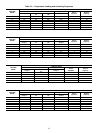
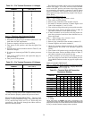
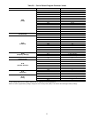
The microprocessor has been programmed to check the
operation of the thermistors. If the measured temperature is
outside of the range of −24 to 225 F or 98,010 to 282 ohms,
then it will be treated as a sensor failure and a diagnostic
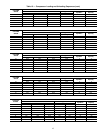
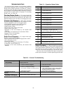
code will be displayed. See Table 17 for sensor temperatures
versus resistance drop. It is also possible to check the op-
eration of the thermistors using the quick test routine.
If a thermistor has failed or the wire is damaged, replace
the complete assembly. Do not attempt to spice the wires or
repair the assembly.
Electronic Controls Checkout — The following will
help determine whether a processor board, a relay board, dis-
play set point board, accessory board, or 2-step demand limit
module is faulty.
Before checking out any board, do the following:
1. At initial start-up, enter the Quick Test mode. This test
will determine if all components are connected and op-
erating properly.
2. If system has been operating and a malfunction occurs,
check display for diagnostic codes. Use diagnostic chart
located on inner panel of access door to control box sec-
tion of unit; this chart will help determine probable cause
of failure.
47