


CODES 59AND 60: LOW-PRESSURE SWITCH — These
codes are used to indicate a low-pressure switch failure.
The processor monitors thelow-pressure switch. If the switch
opens, either by low refrigerant charge, circuit failure, or wir-
ing error, the circuit is locked off. Code 59 indicates a failure
of the lead circuit, and as a result, that circuit will be shut
down. Code 60 indicates a failure of the lag circuit, and as
a result, that circuit will be shut down. These codes will only
be displayed when the display button is pressed. To reset the
circuit, the ON-OFF switch must be turned to OFF, then ON
position.
CODES 63 AND 64: OIL PRESSURE SWITCH — These
codes are used to indicate an oil pressure switch failure. Since
the units do not have oil pressure switches, these codes are
not used. The terminals on the processor board must be jum-
pered together or an error will occur. If these errors occur,
check jumper between J2-1 and J2-2 for a code 63, or be-
tween J2-3 and J2-4 for a code 64 to be sure jumper is prop-
erly connected. To reset the circuit, the ON-OFF switch must
be turned to OFF and then to ON position.
CODE 70: ILLEGAL UNIT CONFIGURATION — If the
unit configuration header is not installed and properly con-
figured, and/or if DIP switches are not properly set, unit will
not start, and an error code of 70 will be indicated on display
board when display button is pushed. Check the header and
DIP switch settings.
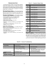
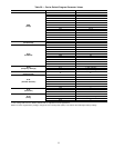
CODES 71 TO 76: THERMISTOR/RESISTOR FAILURE
— If measured temperature of a thermistor is less than
−60 F (363,000 ohms) or greater than 180 F (585 ohms), the
appropriate sensor error code (Table 22) will be displayed
when the display button is pushed.The unit will be shut down.
Thermistor failures will automatically reset once the error
has been corrected. If a failure occurs, the following are pos-
sible causes:
Thermistor or Resistor Failure — A shorted or open ther-
mistor or resistor will cause the failure.
Wiring Failure — If a wiring error exists that causes a shorted
or open circuit, this will cause a failure.
Processor Board Failure — If circuitry on processor board
fails, this could cause an error.
The codes are designated as follows:
Code 71 Supply-Air Thermistor Failure
Code 72 Return-Air Thermistor Failure
Code 73 Not used
Code 74 Not used
Code 75 Circuit 1 Saturated Condensing Thermistor
Code 76 Circuit 2 Saturated Condensing Thermistor
CODE 81: RESET THERMISTOR OR POTENTIOM-
ETER FAILURE — This is a unique code since the reset
temperature potentiometer (P7) is in series with the space
temperature thermistor (T10). If either one of these compo-
nents fail, reset will be terminated. This error will automati-
cally reset once the situation is corrected. If an error is
detected, the most probable cause is one of the following:
• Thermistor Failure — A shorted or open thermistor will
cause the failure.
• Potentiometer Failure — If the potentiometer is outside of
the valid range (40 to 90 F), a failure will result.
• Wiring Problem — If the circuit is open, a failure will be
detected.
• Processor Board Failure — Ifthe processor board fails (hard-
ware), an alarm will be detected.
CODE 82: LEAVING-AIR TEMPERATURE SET POINT
POTENTIOMETER FAILURE — If leaving-air set point po-
tentiometer (P1 — located on display board) fails, control
will use a default value. A failure will cause an error code of
82
to be displayed on display board when display button is
pushed; alarm light will also be energized. A failure is de-
termined by establishing a range of −22 F to 70 F as a valid
range. Anything outside this range will be treated as a fail-
ure. If setting is outside the −22 F to 70 F range, alarm light
82will be energized and an error code of will be displayed
when display button is pushed; the control will use a set point
of 70 F. If set point is between −22 F and 45 F, control will
use a set point of 45 F and no error code will be indicated.
If potentiometer returns to normal, control will automati-
cally reset.
NOTE: The full range of the potentiometer is not used for
the cooling set point range of 45 F to 70 F. The full scale
resistance of the potentiometer is 10 Kohms.
If a failure occurs, one of the following is a probable cause:
Incorrect Potentiometer Setting — Apotentiometer turned fully
clockwise or counterclockwise is outside the valid range and
will cause a failure.
Faulty Wiring — If wiring is incorrect between potentiom-
eter and processor board or display board, a failure will
result.
Potentiometer Failure — If potentiometer is shorted or open,
a failure will result.
CODE 83: ECONOMIZER FEEDBACK POTENTIOM-
ETER FAILURE — If potentiometer on economizer motor
(P2) fails, control will use a default value of 0% and econo-
mizer outdoor-air dampers will close. The failure will en-
83
ergize alarm light and cause an error code of to be dis-
played when display button is pushed. This potentiometer is
a 5 to 15 Kohm potentiometer. If potentiometer returns to
normal, control will automatically reset. If a failure occurs,
one of the following is the probable cause.
Faulty Wiring — If the wiring between processor board and
potentiometer is wrong, this will cause a failure.
Potentiometer Failure — If potentiometer is shorted or open,
this will cause a failure.
Economizer Damper Stuck — The control has been pro-
grammed to indicate an error if potentiometer travel is less
than 10% of the full range. This would happen if dampers or
damper linkage were hung up and could not move
properly.
CODE 84: RESET LIMIT POTENTIOMETER FAILURE
— This code is applicable only if reset is being used. If reset
is being used, DIP switch 2 must be in the ON position. This
potentiometer (P3) is located on the accessory board. If po-
tentiometer setting is less than 0° F or greater than 80 F,
84
alarm light will be energized, a diagnostic code of will
be displayed if display button is pushed, and reset will be
terminated. The full-scale resistance of potentiometer is
10 Kohms, but when installed on the accessory board in par-
allel with the other 2 potentiometers, measured resistance
will be 3.3 Kohms. This failure will automatically reset once
potentiometer returns to normal. If a failure occurs, one of
the following is the probable cause:
DIP Switch Problem — DIP switch 2 is in the ON position
and the accessory board is not installed (accessory board is
standard on these units so it should always be on the unit).
46