


capacity stages to maintain user-established supply-air set
point temperature. When VAV units are also equipped with
optional supply duct pressure controls (either inlet guide vanes
[IGV] or variable frequency drive package),the unit also senses
an increase in duct static pressure and responds by closing
IGV dampers or slowing fan wheel speed to maintain user-
configured set points for supply duct pressure. Allowing the
supply-air temperature to be reset to a higher value main-
tains air circulation in the space without costly overcooling.
The accessory package is required for temperature reset.
The accessory includes:
• thermistor T10, to monitor space temperature
• reset temperature potentiometer P7, to establish start tem-
perature for reset operation
• reset limit potentiometer P3, to establish maximum level
of modified supply-air temperature
More than one space sensor may be used if an average
space temperature is desired for initiating temperature reset.
Refer to installation section for sensor part number and wir-
ing schematic.
Temperature reset will start when space temperature (at
T10) drops to the set point at P7. When Temperature Reset
is active, the LED (light-emitting diode) display will show
21
code . Automatic adjustment of supply-air temperature
set point will end when modified SASP equals reset limit set
point at P3. (See formula for automatic modification of SASP
in Controls Installation, Space Temperature Reset section on
this page.)
CONTROLS INSTALLATION
The VAV units may be used in applications with addi-
tional control features, options, or accessories. Refer to the
appropriate accessory installation instructions for more in-
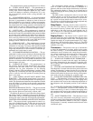
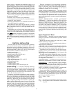
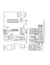
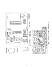
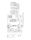
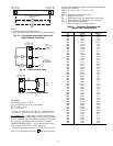
formation on installing that accessory. Unit control box com-
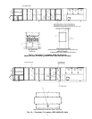
ponent arrangement is shown in Fig. 20-22. Control options
and accessories available for VAV units are:
• smoke control modes
• differential enthalpy sensor
• electric heaters (sizes 034-074 only)
• modulating power exhaust
• Motormaster I control
• space temperature reset
• night setback thermostat (field-supplied)
• single step demand limit
• two-step demand limit
• inlet guide vanes
• variable frequency drive
• variable frequency drive remote display kit
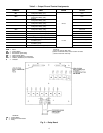
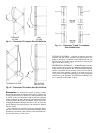
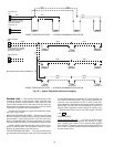
Control Wiring — A switch or timeclock (field sup-
plied) must be wired in to control when unit will go into and
out of Occupied mode. Connect switch or timeclock be-
tween terminals 1 and 2 on terminal block 3 (sizes 034-048)
or terminal block 4 (sizes 054-104) in unit control box. See
Fig. 23. The circuit potential is 24 v.
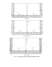
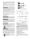
Variable air volume units equipped with warm-up heat re-
quire that room terminals be controlled to go fully open when
unit goes into the Heating mode. Heating interlock relay (HIR)
is provided for this function. The relay is located in the unit
control box. When unit goes into Heating mode, interlock
relay is energized providing switch closure or opening (de-
pending on how field power source is set up) to open the
room terminals. Field connections for interlock relays are
terminals 3 and 4 (for normally open contacts) and terminals
3 and 7 (for normally closed contacts) on terminal block 3
(sizes 034-048) or terminals block 4 (sizes 054-104). See
Fig. 24. Note that a field-supplied power source is required.
There are no required 115-volt field wiring connections,
therefore no provisions have been made in the unit for run-
ning 115-volt wiring. If any of the field-installed options re-
quiring 115-volt connections are desired, the unit must be
modified in the field for 115-volt wiring.
NIGHT SETBACK THERMOSTAT — Wire field-supplied
thermostat (suitable for 24-v circuit) between terminals 1 and
2 on terminal block 3 (sizes 034-048) or terminal block 4
(sizes 054-104). This thermostat is used to bypass the time-
clock occupied/unoccupied switch and is used to operate unit
during unoccupied times at more economical temperatures.
(See Fig. 23.)
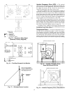
SPACE TEMPERATURE RESET ACCESSORY
(50DJ900021) — Consists of a thermistor (T10) and a reset
board with a potentiometer (P7) that is used to set space tem-
perature at which reset starts. Mount reset board in unit
control box or other convenient place. Wire thermistor in se-
ries with P7 and connect to terminals 12 and 15 on terminal
block 3 (sizes 034-048) or terminal block 4 (sizes 054-104)
in unit control box. If there is a long run to conditioned space,
it is necessary to splice additional wire to thermistor. The
reset board has 2 pressure connectors for field wiring. (See
Fig. 25).
Space Temperature Reset
INSTALLATION — Install the accessory temperature reset
package in accordance with instructions provided with the
accessory kit.
Mount the reset board in the unit control box (or other
suitable location) per instructions.
Locate the thermistor T10 in a suitable location in the oc-
cupied space per instructions.
Wire T10 to the reset board and to the unit control ter-
minal block per Fig. 25. Wire the other terminal on the reset
board to the unit control terminal block per Fig. 25.
If multiple sensors are required to average the space tem-
perature, see Fig. 26. Use only Carrier Part Number
HH79NZ014 sensor, in arrangements of 4 or 9 sensors, with
total wiring not to exceed 1000 ft.
To enable reset function, change DIP (dual in-line pack-
age) switch 2 to position ON. (Disconnect control power be-
fore changing DIP switch positions; reconnect power after
all changes have been made.)
CONFIGURATION — Set points for reset operation are es-
tablished at potentiometers P7 and P3 (on the reset board).
Potentiometer P7 — Reset temperature set point (tempera-
ture at which reset function will start). Maximum of 80 F,
minimum 0° F. Set below normal room cooling set point level
to sense overcooling in the occupied space.
NOTE: It is difficult to accurately set the P7 potentiometer
to the desired set point. Use the procedure below.
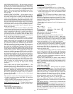
Proper setting of the P7 potentiometer may be made on a
resistance basis. The microprocessor initiates reset when it
detects a resistance of the thermistor plus the potentiometer
of 13,084 ohm. The potentiometer set point may be calcu-
lated using the following formula:
P7
R
= 13,084 – T10
R
Where:
P7
R
= the desired set point of the P7 potentiometer in ohms
T10
R
= the resistance of the T10 thermistor for the desired
set point
13