


Diagnostic Codes — Diagnostic codes are warnings
of abnormal or fault conditions, and may cause either one
circuit or the whole unit to shut down. They are assigned
code numbers as described below.
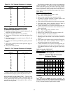
Table 22 contains a description of each diagnostic code
error and possible cause. Manual reset is accomplished by
moving the ON/OFF Switch to the OFF position, then back
to ON.
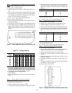
The 2-digit LED display is used to display the diagnostic
codes and the alarm light (located next to display) is ener-
gized whenever a diagnostic code is tripped. When a prob-
lem is suspected, always check the display first for diagnos-
tic information.
NOTE: Codes 53, 54, 57, 58, 61, 62, 65-69, 73, 74, and 77-80
are not used on these units.
IMPORTANT: The microprocessor memory and the
display will be cleared if the power to the microproces-
sor is shut off. DO NOT attempt to bypass, short, or
modify the control circuit or electronic boards in any
way to correct a problem. This could result in a haz-
ardous operating condition.
CODES 51, 52, 55, 56: COMPRESSOR FAILURE — If con-
trol relay (CR) opens while compressor should be operating,
compressor will stop and microprocessor will energize alarm
51
52 55 56light and display a code of , , or (de-
pending on compressor) when display button is pushed. The
compressor will be locked off; to reset, the ON-OFF switch
must be turned to OFF and then to ON position.
If lead compressor in a refrigerant circuit is shut down,
the other compressor in that circuit will also be shut down
and locked off. Only the error code for the lead compressor
will be displayed.
Code 51 is for compressor 1, and Code 55 is for com-
pressor 2. Codes 52 and 56 are used for compressors 3 and
4, respectively, on size 104 units.
The microprocessor has also been programmed to indi-
cate a compressor failure if CR switch is closed when com-
pressor is not supposed to be on.
If a failure occurs, the following are possible causes:
High-Pressure Switch Open — The high-pressure switch for
each compressor is wired in series with 24-v power that en-
ergizes CR. If high-pressure switch opens during operation,
CR will stop compressor and this will be detected by micro-
processor through the feedback contacts.
Internal Thermostat — The internal thermostat in each 06D
compressor is also wired in series with 24-v power that en-
ergizes CR. If thermostat fails or switch opens during op-
eration of compressor, compressor will shut down and fail-
ure is detected through feedback contacts (size 034 and 038
only).
CR Failure — If CR fails with large relay eitheropen or closed,
microprocessor will detect this, lock compressor off, and in-
dicate an error.
Relay Board Failure — If small 24-v relay on the relay board
fails, microprocessor will detect this through feedback con-
tacts and indicate an error.
Processor Board Failure — If hardware that monitors feed-
back switch fails and processor board fails to energize the
relay board relay to ON position, an error may be indicated.
The control does not detect compressor circuit breaker
failures.
Wiring Problem — A wiring error or a loose wire may cause
the feedback circuit to be broken.
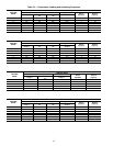
Table 22 — Diagnostic Codes
DISPLAY DESCRIPTION OF FAILURE ACTION TAKEN
BY CONTROL
RESET
METHOD
PROBABLE CAUSE
51
55
52
56
Compressor 1 failure
Compressor 2 failure
Compressor 3 failure
Compressor 4 failure
Circuit 1 shut off
Circuit 2 shut off
Compressor 3 shut off
Compressor 4 shut off
Manual
Manual
Manual
Manual
High-pressure switch or high dis-
charge gas thermostat switch
trip, compressor ground current
Ͼ 2.5 amp or compressor board
relay on when it is not supposed
to be on. Wiring error between
electronic control and compres-
sor protection module.
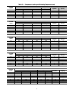
59
60
Loss-of-charge circuit 1
Loss-of-charge circuit 2
Circuit 1 shut off
Circuit 2 shut off
Manual
Manual
This indicates either a low refrig-
erant charge, or a loss-of-charge
switch failure.
63
64
Low oil pressure circuit 1
Low oil pressure circuit 2
Circuit 1 shut off
Circuit 2 shut off
Manual
Manual
Not used; Check jumper on pro-
cessor board.
70 Illegal unit configuration Unit will not start Manual Configuration error (see Note 1).
71
72
75
76
81
Supply-air thermistor failure
Return-air thermistor failure
Circuit 1 saturated condensing thermistor
Circuit 2 saturated condensing thermistor
Reset temperature thermistor failure
Unit shut off
Use default value
Unit shut off
Unit shut off
Stop reset
Auto.
Auto.
Auto.
Auto.
Auto.
Thermistor or resistor failure, wir-
ing error, or thermistor or resistor
not connected to the processor
board.
82
83
84
85
86
87
Leaving-air set point potentiometer failure
Economizer potentiometer failure
Reset limit set point potentiometer failure
Demand limit potentiometer failure
Minimum economizer potentiometer failure
Warm-up set point potentiometer failure
Use default value
Close economizer
Stop reset
Stop demand limit
Close economizer
Use default value
Auto.
Auto.
Auto.
Auto.
Auto.
Auto.
Potentiometer improperly con-
nected, potentiometer setting out
of range, potentiometer failure or
wiring error.
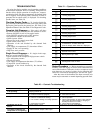
NOTES:
1. Illegal unit configuration caused by missing programmable header or both unloader DIP switches on.
2. All auto. reset failures that cause the unit to stop will restart when the error has been corrected.
3. All manual reset errors must be reset by turning the control switch off and then back on.
4. Valid resistance range for the thermistors is 363,000 to 585 ohms.
5. Codes 53, 54, 57, 58, 61, 62, 65-69, 73, 74, and 77-80 are not used on these units.
45