


VFD Operation — When troubleshooting the VFD, check
first that all required conditions for VFD operation are
satisfied.
For the VFD to run, the following conditions must be met
at the VFD:
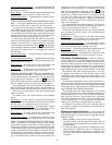
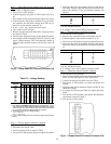
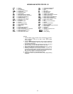
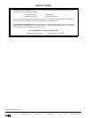
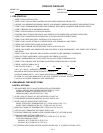
1. Drive enable jumper is installed from terminals CC-ST
(factory supplied) (see Fig. 53 and 54).
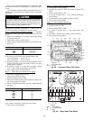
2. Proper rotation jumper is installed at terminals R-CC (re-
verse rotation, factory supplied) or terminals F-CC (for-
ward rotation, factory supplied).
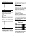
UNIT SIZES ROTATION JUMPER
034-048 Reverse R-CC
054-074 Forward F-CC
078-104 Forward F-CC
3. Emergency stop jumper is installed from terminals S4-CC
(factory supplied).
4. A4 to 20 mAsignal is applied across terminals IV-C (from
pressure transducer, factory supplied).
5. DIP switch SW1 (located on the VFD’s printed circuit
control panel) must be set to ‘‘I’’ (indicating usage of a
4 to 20 mA input signal at terminals ‘‘IV’’).
6. Speed Control (located on the VFD’s keypad/display) set
for ‘‘Remote’’ (press the ‘‘Speed Ctrl’’ button until LED
‘‘Remote’’ is illuminated).
7. Programmed according to Carrier defaults.
8. Duct Pressure set point established by user, or use fac-
tory default (30 Hz indicating 2.50-in. wg) (see Table 13).
VFD Operational Status — The VFDs contain ex-
tensive self-diagnostic functions which are accessed through
the VFD display panel (located on the front of the VFD or
at a remote location when the accessory remote display pack-
age has been installed).
If using the VFD display panel, disconnect all power
to the unit and the VFD before entering unit, or use
the accessory remote display module. Disable supply fan
and motor operation before accessing VFD-mounted dis-
play module.
When power is first supplied to the VFD, the display au-
tomatically starts with the frequency monitor function of its
standard monitor mode. In the frequency monitor function,
the output frequency is displayed. Push the S/P/M (Setup/
Program/Monitor)key to switch to the Mode Selection menu.
Push the S/P/M key again to toggle the display back to the
standard monitor mode.
From the Mode Selection menu, the service person can
view all of the monitored status variables, including up to
four user-selected variables and any trip history in the memory.
Refer to the separate VFD Operation Manual for detailed
instructions on accessing diagnostic information, initiating
troubleshooting, and clearing any trip history.
Restoring Factory VFD Defaults — The original
factory configuration values are saved in the memory of the
VFD and can be restored by the service person if required.
There are two types of saved file data: Carrier-factory set-
tings (factory programmed settings made to the VFD which
apply specifically to the unit it is installed on) and standard
defaults for general Carrier unit use.
The Carrier-factory settings are maintained as user set-
tings. These can be restored by entering the Setup mode (in
the S/P/M menu) and setting parameter tYP= 6 on the keypad/
display. This will recall the specific factory defaults for this
unit.
Occasionally it may be necessary to restore the VFD de-
faults to the general Carrier use values. These are stored in
an OPTION ROM (read-only memory chip). However, some
variables may need to be manually changed to match the
specific unit’s factory default settings. To recall the general
Carrier defaults, enter the Setup mode and set parameter
tYP = 3. Refer to Table 30 for items requiring manual
adjustment.
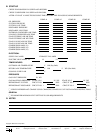
Table 30 — Required User Adjusted Defaults
SIZES ITEM
All Motor overload settings (see Table 31)
054-104
1. Check jumper CC-F
2. Gr.UT/bLSF = 1
3. Gr.SF/Sr.n = 1
4. Gr.SF/SrN1 = 0
5. SEtP/tYP = 5 (Save User Settings)
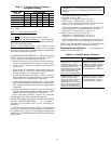
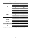
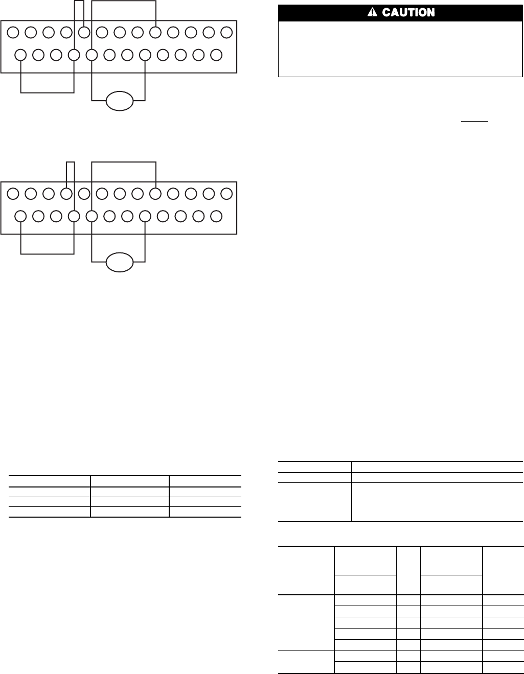
Table 31 — Motor Overload Settings
UNIT 48/50
UNIT
VOLTAGE
DESIGNATION
AND
IFM HP
DESIGNATION
tHr1
SETTING
Model No.
Position 12
Model No.
Position 15
FK,FY, JK,JY 5 And N 82.0
5 And Q 86.0
6 And A 80.0
6 And K 80.0
6 And Q 80.0
FKX,FKY,
JKX,JKY
6 And Q 80.0
6 And T 78.0
LEGEND
IFM — Indoor Fan Motor
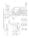
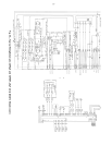
Unit Wiring — A typical wiring schematic is shown in
Fig. 55.
P24
RES
RR
F
ST
FM
AM
CC
CC
R
SI
RX
S2
S3
PP
S4
RCH
P24
LOW
LOW
FLA
FLB
FLC
FP
IV
4-20mA
Fig. 53 — Variable Frequency Drive Terminal Block
(Size 034-048 Units)
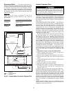
P24
RES
RR
F
ST
FM
AM
CC
CC
R
SI
RX
S2
S3
PP
S4
RCH
P24
LOW
LOW
FLA
FLB
FLC
FP
IV
4-20mA
Fig. 54 — Variable Frequency Drive Terminal Block
(Size 054-104 Units)
54