


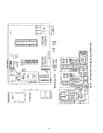
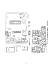
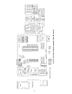
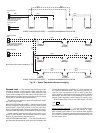
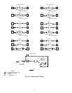
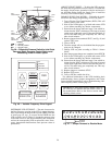
INSTALLATION — To enable one or more of the possible
smoke control modes available with these units, determine
the switches required for the desired mode(s) from Table 6,
field-supply and install the appropriate switches and field wire
per Fig. 32. Switch functions are shown in Table 7.
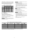
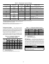
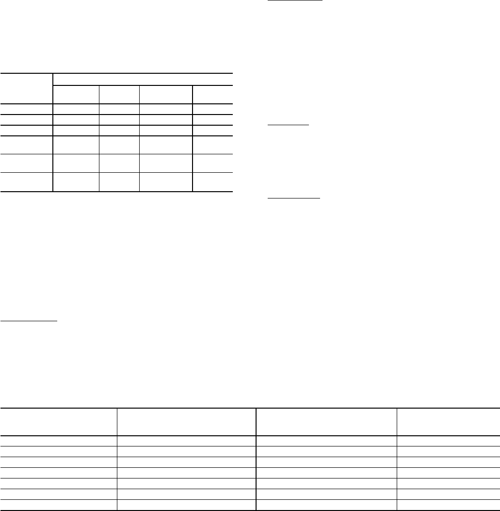
Table 5 — Smoke Control Modes
FUNCTION
MODE
Fire
Shutdown
Pressur-
ization
Evacuation*
Smoke
Purge*
Supply Fan Off On Off On
IGV/VFD† — Open/On — Open/On
Economizer Closed Open Open Open
Return Air
Damper
Open Closed Closed Closed
Exhaust
Fans
Off Off On On
Exhaust
Damper
Closed Closed Open Open
LEGEND
IGV — Inlet Guide Vane
VAV — Variable Air Volume
VFD — Variable Frequency Drive
*Power exhaust option/accessory required for this mode.
†Applicable to VAV units with appropriate options.
CONFIGURATION — No set points required for Smoke Con-
trol modes. Modes are activated by energizing all switches
appropriate for each Smoke Control mode.
OPERATING SEQUENCE
Fire Shutdown — At command from the field switches (see
Table 5), all unit operation (cooling, heating, supply fan and
power exhaust) will terminate.
Pressurization — At command from the field switches for
Pressurization mode (see Table 5):
1. Economizer dampers will open
2. The HIR function will energize, opening room terminals
to full-open (heating) positions.
3. Supply fan will run. (If equipped with IGV: control vanes
will open. If equipped with VFD: the VFD will control to
duct static set point or best available with all terminals
open.)
4. Power exhaust dampers (if equipped) will close.
5. Power exhaust fans (if equipped) will turn off.
Evacuation — At command from thefield switches for Evacu-
ation mode (see Table 5):
1. Supply fan will turn off.
2. Economizer dampers will open.
3. Exhaust fans will run at maximum capacity.
4. Exhaust dampers will open.
Smoke Purge — At command from the field switches for
Smoke Purge mode (see Table 5):
1. Economizer dampers will open.
2. The HIR function will energize, opening room terminals
to full-open (heating) positions.
3. Supply fan will run. (If equipped with IGV: Control vanes
will open. If equipped with VFD: the VFD will control to
duct static set point or best available with all terminals
open.)
4. Exhaust fans will run at maximum capacity.
5. Exhaust dampers will open.
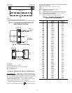
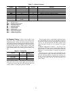
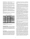
Table 6 — Smoke Control Switches Required for Each Mode
FIRE
SHUTDOWN
PRESSURIZATION
EVACUATION
(Modulating Power
Exhaust)
SMOKE
PURGE
SW-1 SW-1 SW-1 SW-1
SW-2 SW-2 SW-2 SW-2
SW-4 SW-3 SW-3
SW-5 SW-5 SW-4
SW-6 SW-6 SW-9A/B
SW-9A/B SW-7
SW-8
NOTE: All switches are shown in ‘‘as installed’’ (power OFF or deenergized) position. In these positions, none of these
modes will be activated; normal unit operation is permitted by the base unit controls. To initiate any mode, all switches listed
under this mode in the table must be energized, causing the depicted contact position to change from depicted positions to
energized positions. Switches may be manually or electrically operated.
22