


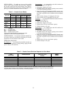
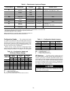
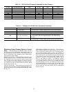
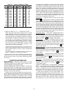
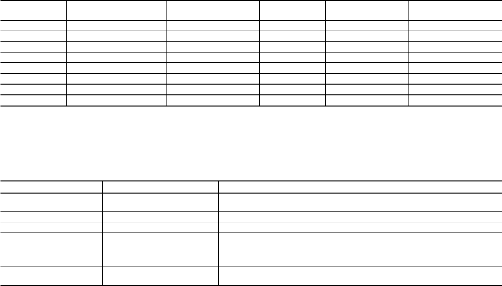
Table 13 — VFD Set Point (Frequency Command) for Duct Pressure
PRESSURE
(in. wg)
VFD SET POINT (Hz)
CONTROL SIGNAL
(mA)
PRESSURE
(in. wg)
VFD SET POINT
(Hz)
CONTROL SIGNAL
(mA)
0.00 0 4.0 2.00 24 10.4
0.25 3 4.8 2.25 27 11.2
0.50 6 5.6 2.50 30 12.0
0.75 9 6.4 2.75 33 12.8
1.00 12 7.2 3.00 36 13.6
1.25 15 8.0 3.25 39 14.4
1.50 18 8.8 3.50 42 15.2
1.75 21 9.6
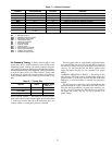
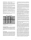
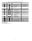
Table 14 — Changing the VFD Set Point (Frequency Command)*
KEY OPERATION LED MESSAGE EXPLANATION
XX.X or OFF
Standard Monitor Mode (output frequency). If drive is disabled, display
will read ЉOFFЉ. If enabled, display will show current output frequency
↓ 60.0 Pressing arrow key once will display the current frequency setpoint
↓↑ 45.0 (flashing) Pressing up/down arrow keys changes the desired setpoint
R/W FC and 45.0 (flashing)
When R/W is pressed, the parameter name (FC) and the new value
(45.0) will alternately flash to indicate that the new value has been
stored. After 2 cycles, the display will return to the standard monitor
mode.
XX.X or OFF
Standard Monitor Mode (output frequency). If drive is disabled, display
will read ЉOFFЉ. If enabled, display will show current output frequency
*Choose set point from Table 13 according to desired duct pressure.
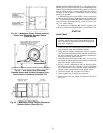
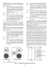
Modulating Power Exhaust (Option or Acces-
sory)
— The Modulating Power Exhaust system will main-
tain space pressure by modulating power exhaust fan no. 1
and staging power exhaust fan no. 2. Building pressure set
point is established at the modulating power exhaust differ-
ential pressure switch (DPS).
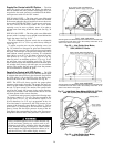
SIZE 034-048 UNITS — The modulating power exhaust dif-
ferential pressure switch is located in the auxiliary control
box mounted in the corner next to the power exhaust motor
door. To gain access to this control box, remove the auxil-
iary control box cover. When replacing cover, be sure to prop-
erly secure it in order to prevent water from being drawn
into the unit. See Fig. 33.
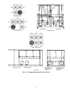
SIZE 054-104 UNITS — The modulating power exhaust dif-
ferential pressure switch is mounted below the auxiliary con-
trol box next to the access door labeled FILTER SECTION.
See Fig. 35.
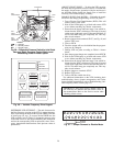
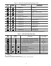
DIFFERENTIAL PRESSURE SWITCH — The modulating
power exhaust DPS has a set point range of 0.5 in. wg to
−0.5 in. wg. Factory setting is +0.1 in. wg. To adjust set point,
turn set point adjusting screw (see Fig. 39) clockwise to
decrease set point and counterclockwise to increase set point.
This switch also has an adjustable null span. The null span
is the pressure change that can be made without contacts
opening or closing. It is adjustable from 0.06 in. wg to
0.14 in. wg when set point is at minimum position
(−0.5 in. wg) and 0.07 in. wg to 0.14 in. wg when set point
is at maximum position (+0.5 in. wg). To adjust null span,
turn null adjusting screw (Fig. 39) clockwise to decrease span
and counterclockwise to increase span. All switches leave
factory with null span set at maximum position. The smaller
the null span, the closer the pressure will be maintained to
desired set point.
30