


Supply Fan Control with IGV — In most VAV units,
the supply fan static pressure is controlled by inlet guide vanes.
The inlet guide vanes operate independently from the micro-
processor. The supply static pressure is controlled by a dif-
ferential pressure switch. If the unit is equipped with a re-
turn fan, building pressure is controlled by another differential
pressure switch.
For example, assume that set point on supply fan differ-
ential switch is 1.9 in. wg. If pressure in supply duct goes
above 1.9 in. wg, switch will make to the normally open
contact and energize inlet guide vane motor to drive inlet
guide vanes to a more closed position, thus reducing airflow
and lowereing duct pressure. Once setpoint pressure is reached,
switch will open and deenergize inlet guide vane motor. If
pressure in supply duct is below 1.9 in. wg, the switch will
make to the normally closed contact and energize inlet guide
vane motor to drive inlet guide vane to a more open posi-
tion; increasing airflow and raising duct pressure. Once again,
once desired pressure has been reached, switch will open and
deenergize inlet guide vane motor. How far above or below
the set point setting the switch goes before energizing de-
pends on setting of null span (null span is pressure change
that can be made without contacts opening or closing). If
null span is at maximum position, pressure will vary from
0.17 in. wg to 0.31 in. wg depending on set point (if set point
is at minimum setting, null span will be 0.17 in. wg, while
if it is at maximum position, the null span will be
0.31 in. wg) before switch acts. If null span is adjusted to a
minimum setting, duct pressure will vary from 0.06 in. wg
to 0.11 in. wg (again depending on switch set point) before
switch acts. Setting null span to minimum position will re-
sult in a smaller pressure fluctuation than if it is set at maxi-
mum position.
Supply Fan Control with VFD — When equipped
with the VFD option, the supply fan static pressure is con-
trolled by modulating the fan wheel speed. The VFD oper-
ates independently from the microprocessor. Aduct pressure
transducer monitors duct static pressure. The transducer out-
put (4 to 20 mA) is directed into the VFD. The VFD adjusts
supply fan motor speed (which changes wheel speed) as mea-
sured duct pressure varies from set point as established at
the VFD. The VFD will modulate fan speed until the duct
pressure set point is achieved.
NOTE: The VFD will always provide the proper phase se-
quence to the supply fan motor. This motor will operate in
proper rotation regardless of the phase sequence to the unit.
If, upon start-up, the outdoor fans operate backwards but the
indoor fan operates in the correct direction, reverse any two
leads to the main terminal block. All fans will then operate
in the correct direction.
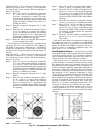
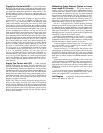
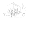
Modulating Power Exhaust (Option or Acces-
sory except FY,JY units)
— The power exhaust as-
sembly consists of two parallel and independent belt-drive
forward curve fans. The fans, motors, and drives are located
over the return air opening of the unit, in a plenum beneath
the outside air intake plenum. The fans discharge air hori-
zontally out the back of the unit through individual baro-
metric backdraft dampers with hoods. (See Fig. 44 and 45.)
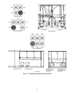
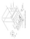
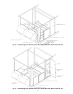
Operation is interlocked with economizer operation. Sheet
metal installation is shown in Fig. 46 and 47.
Fan no. 1 is equipped with a variable position discharge
damper located in the outlet of the fan housing. This damper
is controlled by an actuator (PEDM), based on signals from
the building pressure differential pressure switch (DPS). Avail-
able range on the DPS is −0.50 to +0.50 in. wg, adjustable.
Building pressure is sensed by a pick-up (field-supplied and
-installed) located in the occupied space.
Operation of the modulating power exhaust is a combi-
nation modulating/staged control, with fan no. 1 providing
modulating control from 0 to 100%, and fan no. 2 being staged
On/Off according to damper position on fan no. 1.
As the economizer actuator opens past 17% open, auxil-
iary switch DMS1 closes, energizing fan contactor PEC1.
Fan motor no. 1 starts and runs.
Capacity of fan no. 1 is controlled by the position of the
outlet damper. As building pressure increases above set point,
the DPS will close its contact and drive the power exhaust
damper motor (PEDM) open until set point is achieved. DPS
then opens its control contacts and PEDM maintains current
position.
When space demand moves PEDM to 90% of full-open
position, auxiliary switch PEDMS closes, energizing fan con-
tactor PEC2. Fan motor no. 2 starts and runs. Increased ex-
haust airflow will lower space pressure, causing DPS to drive
PEDM back towards its closed position, until the set point
is achieved.
If space pressure decreases until PEDM position is re-
duced to 10% of open position, PEDMS will open, deener-
gizing fan contactor PEC2 and shutting off fan no. 2.
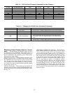
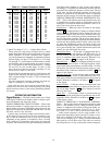
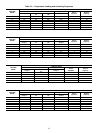
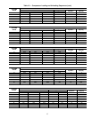
Unit Staging — Compressor loading and unloading se-
quences are shown in Table 19.
38