


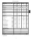
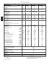

8
Step 5 —Make Electrical Connections
ELECTRICAL SHOCK HAZARD
Failure to foll ow this war ning could result in p ersonal
injur y or deat h,
Unit cabi net must have an unint errupt ed, unbroke n
electrical ground to mi nimize t he possibility of personal
injury if an electrical fault shoul d oc cur. This ground may
consist of e le ctri cal wire connected to uni t ground lug in
control compa rtm ent, or conduit approved f or electrica l
ground when install ed in accordance with NEC (National
Electrical Code), ANSI/NFP A (National Fire Protection
Association), latest edition, and local electrical codes. Do
not use gas pi ping as an ele ctri cal ground.
!
WARNING
Field Power Supply
All units except 208/230-v units are factory wired for the voltage
shown on the nameplate. If the 208/230-v unit is to be connected
to a 208-v power supply, the transformer must be rewired by
disconnecting the black wire from the 230-v 1/4 --in. terminal on
the transformer and connecting it to the 200-v 1/4--in. terminal
from the transformer.
Refer to unit label diagram for additional information. Pigtails
are provided for field service. Use factory-supplied splices or UL
(Underwriters’ Laboratories) approved copper connector.
When installing units, provide a disconnect per NEC.
All field wiring must comply with NEC and local
requirements.
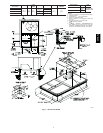
Install field wiring as follows:
1. Install conduit through side panel openings. For units
without electric heat, install conduit between disconnect
and control box.
2. Install power lines to terminal connections as shown in
Fig. 12.
3. For units with electric heat, refer to Accessory Electric
Heat Installation Instructions.
During operation, voltage to compressor terminals must bewithin
range indicated on unit nameplate (also see Table 3 and 4). On
3--phase units, voltages between phases must be balanced within
2% and the current within 10%. Use the formula shown in Table
3 and 4, Note 2, to determine the percentage of voltage
imbalance. Operation on improper line voltage or excessive phase
imbalance constitutes abuse a nd may cause damage to electrical
components. Such operation invalidates any applicable Carrier
warranty.
NOTE: If accessory thru-the-bottom connections and roof curb
are used, refer to the Thru-the-Bottom Accessory Installation
Instructions for information on wiring the unit.
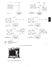
Field Control W
iring
Install a Carrier-approved accessory thermostat assembly
according to installation instructions in cluded with the accessory.
Locate thermostat assembly on a solid wall in the conditioned
space to sense average temperature in accordance with thermostat
installation instructions.
Route thermostat cable or equivalent single leads of colored wire
from subbase terminals through connector on unit to low-voltage
connections (shown in Fig. 10 and 11).
NOTE: For wire runs up to 50 ft, use no. 18 AWG (American
Wire Gauge) insulated wire (35_Cminimum).For50to75ft,use
no. 16 AWG insulated wire (35_C minimum). For over 75 ft, use
no. 14 AWG insulated wire (35_C minimum). All wire larger
than no. 18 AWG cannot be directly connected to the thermostat
and will require a junction box and splice at the thermostat.
1. Connect thermostat wires to screw terminals of lowvoltage
terminal board.
2. Pass the control wires through the hole provided in the
control box.
3. Some models may be equipped with a raceway built into
the corner post on the left side of control box (See Fig.
13.) This raceway provides the required c learance between
high--voltage and low voltage wiring. For models without
a raceway, ensure to provide the NEC required c learance
between high--voltage and low--voltage wiring.
Heat Anticipator
Settings
Set heat anticipator settings at 0.8 amp for first stage and 0.3 for
second stage heating.
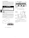
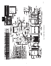
WIRE
CONNECTIONS
TO
LOW-VOLTAGE
SECTION
COOL STAGE 1
FAN
HEAT STAGE 1
COOL STAGE 2
HEAT STAGE 2
24 VAC HOT
24 VAC COM
N/A
OUTDOOR AIR
SENSOR
Y1/W2
G
W/W1
Y/Y2
O/W2
R
C
S1
S2
THERMOSTAT DIPSWITCH SETTINGS
R
G
Y1
Y2
W1
W2
C
IPD/X
ON
OFF
A
B
C
D
LEGEND
NOTE: Underlined letter indicates active thermostat output when
configured for A/C operation.
Field Wiring
C06008
Fig. 10 --- Low--Voltage connections With or
Without Economizer or Two--Position Damper
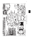
W2
C
Y1
G
R
Y2
W1
C
G
R
Y2
W1
X
W2
C
Y1
G
R
Y2
W1
X
24 VAC
RMTOCC
CMPSAFE
FSD
NOT USED
C
X
SFS
THERMOSTAT CONTROL
CONNECTION
BOARD
BOARD
CONNECTION
CONTROL
C06009
Fig. 11 --- Low --Voltage Connections
(Units with PremierLinkt Contro ls)
50HE,HJ