


67
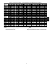
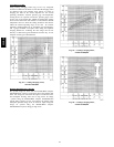
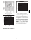
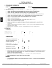
50HE -- 5 TON CHARGING CHART
55.0
65.0
75.0
85.0
95.0
105.0
115.0
42 47 52 57 62 67 72 77
SuctionLineTemp(degF)
SuctionLinePressure(psig)
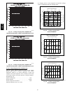
310.0
410.0
510.0
610.0
710.0
810.0
0.0 5.0 10.0 15.0 20.0 25.0
SuctionLineT emperature (degC)
SuctionLinePressure(kpa)
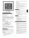
FC
115 46
105 41
95 35
85 29
75 24
C06151
Fig. 69 --- Cooling C harging Chart,
Standard 50HE006
To Use Cooling Charging Charts, Units W
ith
Humidi--Mizer
Adaptive Dehumidification System
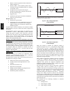
Refer to charts (Fig. 62-65) to determine the proper leaving
condenser pressure and temperature.
Example (Fig. 62):
Leaving Condenser Pressure 250 psig.................
Leaving Condenser Temperature 105_F...............
NOTE: When using the charging charts, it is important that only
the subcooling/reheat dehumidification coil liquid line solenoid
valve be energized. The subcooling/reheat dehumidification coil
liquid line solenoid valve MUST be energized to use the charging
charts and the outdoor motor speed controller jumpered to run the
fanatfullspeed.
IMPORTANT: Refer to Troubleshooting Tables for additional
information.
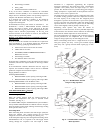
Step 6 —Replacement Parts
A c omplete list of replacement parts may be obtained from any
Carrier distributor upon request.
TROUBLESHOOTING
Step 1 —Unit Troubleshooting
Refer to Tables 34-38 for unit troubleshooting details.
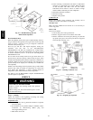
Step 2 —Economi$er IV Troubleshooting
See Table 39 for EconoMi$er IV logic.
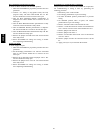
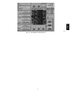
A functional view of the EconoMi$er IV is shown in Fig. 67.
Typical settings, sensor ranges, and jumper positions are also
shown. An EconoMi$er IV simulator program is available from
Carrier to help with EconoMi$er IV training and
troubleshooting.
Economi$er IV Pr
eparation
This procedure is used to prepare the EconoMi$er IV for
troubleshooting. No troubleshooting or testing is done by
performing the following procedure.
NOTE: This procedure requires a 9-v battery, 1.2 kilo-ohm
resistor, and a 5.6 kilo-ohm resistor which are not supplied with
the EconoMi$er IV.
IMPORTANT: Be sure to record the positions of all
potentiometers before starting troubleshooting.
1. Disconnect power at TR and TR1. All LEDs should be
off. Exhaust fan contacts should be open.
2. Disconnect device at P and P1.
3. Jumper P to P1.
4. Disconnect wires at T and T1. Place 5.6 kilo-ohm resistor
across T and T1.
5. Jumper TR to 1.
6. Jumper TR to N.
7. If connected, remove sensor from terminals S
O
and +.
Connect 1.2 kilo-ohm 4074EJM checkout resistor across
terminals S
O
and +.
8. Put 620-ohm resistor across terminals S
R
and +.
9. Set minimum position, DCV set point, and exhaust
potentiometers fu lly CCW (counterclockwise).
10. Set DCV maximum position potentiometer fully CW
(clockwise).
11. Set enthalpy potentiometer to D.
12. Apply power (24 vac) to terminals TR and TR1.
Differential
Enthalpy
To check differential enthalpy:
1. Make sure EconoMi$er IV preparation procedure has been
performed.
2. Place 620-ohm resistor across S
O
and +.
3. Place 1.2 kilo-ohm resistor across S
R
and +. The Free
Cool LED should be lit.
4. Remove 620-ohm resistor across S
O
and +. The Free Cool
LED should turn off.
5. Return EconoMi$er IV settings and wiring to normal
after completing troubleshooting.
Single
Enthalpy
To check single enthalpy:
1. Make sure EconoMi$er IV preparation procedure has been
performed.
2. Set t he enthalpy potentiometer to A (fully CCW). The
Free Cool LED should be lit.
3. Set the enthalpy potentiometer to D (fully CW). The Free
Cool LED should turn off.
4. Return EconoMi$er IV settings and wiring to normal
after completing troubleshooting.
DCV (Demand Controlled Ventilation) and Power
Exhaust
To check DCV and Power Exhaust:
1. Make sure EconoMi$er IV preparation procedure has been
performed.
2. Ensure terminals AQ and AQ1 are open. The LED for
both DCV and Exhaust should be off. The actuator should
be fully closed.
3. Connect a 9-v battery to AQ (positive node) and AQ1
(negative node). The LED for both DCV and Exhaust
should turn on. The actuator should drive to between 90
and 95% open.
4. Turn the Exhaust potentiometer CW until the Exhaust
LED turns off. The LED should turn off when the
potentiometer is approximately 90%. The actuator should
remain in position.
5. Turn the DCV set point potentiometer CW until the DCV
LED turns off. The DCV LED should turn off when the
potentiometer is approximately 9 v. The actuator should
drive fully closed.
6. Turn the DCV and Exhaust potentiometers CCW until the
Exhaust LED turns on. The exhaust contacts will close 30
to 120 seconds after the Exhaust LED turns on.
7. Return EconoMi$er IV settings and wiring to normal
after completing troubleshooting.
50HE,HJ