


68
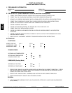
DCV Minimum and Maximum
Position
To check the DCV minimum and maximum position:
1. Make sure EconoMi$er IV preparation procedure has been
performed.
2. Connect a 9-v battery to AQ (positive node) and AQ1
(negative node). The DCV LED should turn on. The
actuator should drive to between 90 and 95% open.
3. Turn the DCV Maximum Position potentiometer to
midpoint. The actuator should drive to between 20 and
80% open.
4. Turn the DCV M aximum Position potentiometer to fully
CCW. The actuator should drive fully closed.
5. Turn the Minimum Position potentiometer to midpoint.
The actuator should drive to between 20 and 80% open.
6. Turn the Minimum Position Potentiometer fully CW. The
actuator should drive fully open.
7. Remove the jumper from TR and N. The actuator should
drive fully closed.
8. Return EconoMi$er IV settings and wiring to normal
after completing troubleshooting.
Supply--Air
Input
To check supply-air input:
1. Make sure EconoMi$er IV preparation procedure has been
performed.
2. Set the Enthalpy potentiometer to A. The Free Cool LED
turn s on. The actuator should drive to between 20 and
80% open.
3. Remove the 5.6 kilo-ohm resistor and jumper T to T1. The
actuator should drive fully open.
4. Remove the jumper across T and T1. The actuator should
drive fully closed.
5. Return EconoMi$er IV settings and wiring to normal
after completing troubleshooting.
Economi$er IV Troubleshooting
Completion
This procedure is used to return the EconoMi$er IV to operation.
No troubleshooting or testing is done by performing the
following procedure.
1. Disconnect power at T R and TR1.
2. Set enthalpy potentiometer to previous setting.
3. Set DCV maximum position potentiometer to previous
setting.
4. Set minimum position, DCV set point, and exhaust
potentiometers to previous settings.
5. Remove 620-ohm resistor from terminals S
R
and +.
6. Remove 1.2 kilo-ohm checkout resistor from terminals S
O
and +. If used, reconnect sensor from terminals S
O
and +.
7. Remove jumper from TR to N.
8. Remove jumper from TR to 1 .
9. Remove 5.6 kilo-ohm resistor from T and T1. Reconnect
wires at T and T1.
10. Remove jumper from P to P1. Reconnect device at P and
P1.
11. Apply power (24 vac) to terminals TR and TR1.
50HE,HJ