


31
C06131
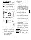
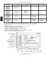
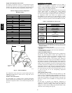
Fig. 20 --- Outdoor--Air Damper With
Hood Attached
C06132
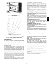
Fig. 21 --- Outdoor--Air Damper Position Setting
Premierlink
Control
The PremierLink controller is compatible with Carrier Comfort
NetworkR (CCN) devices. This control is designed to allow
users the access and ability to change factory--defined settings,
thus expanding the function of the standard unit control board.
Carrier’s diagnostic standard tier display tools such as
Navigatort or Scrolling Marquee can be used with the
PremierLink controller.
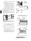
The PremierLink controller (see Fig. 22 and 23) requires the use
of a Carrier electronic thermostat or a CCN connection for time
broadcast to initiate its internal tim eclock. This is necessary for
broadcast of time of day functions (occupied/unoccupied). No
sensors are supplied with the field--mounted PremierLink control.
The factory --installed PremierLink control includes only the
supply--air temperature (SAT) sensor and the outdoor air
temperature (OAT) sensor as standard. An indoor air quality
(CO2) sensor can be added as an option. Refer to Table 5 for
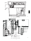
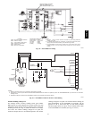
sensor usage. Refer to Fig. 24 for PremierLink controller wiring.
The PremierLink control may be mounted in the control panel or
an area below the control panel.
NOTE: PremierLink controller versions 1.3 and later are shipped
in Sensor mode. If used with a thermostat, the PremierLink
controller must be configured to Thermostat mode.
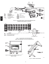
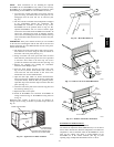
Install the Supply Air Temperature (SAT) Sensor
When the unit is supplied with a factory--mounted PremierLink
control, the supply --air temperature (SAT) sensor
(33ZCSENSAT) is factory--supplied and wired. The wiring is
routed from the PremierLink control over the control box,
through a grommet, into the fan section, down along the back
side of the fan, and along the fan deck over to the supply--air
opening.
The SAT probe is wire--tied to the supply--air opening (on the
horizontal opening end) in its shipping position. Remove the
sensor for installation. Re--position the sensor in the flange of the
supply--air opening or in the supply air duct (as required by local
codes). Drill or punch a 1/2--in. hole in the flange or duct. Use
two field--supplied, self--drilling screws to secure the sensor probe
in a horizontal orientation.
NOTE: The sensor must be mounted in the discharge airstream
downstream of the cooling coil and any heating devices. Be sure
the probe tip does not come in contact with any of the unit or heat
surfaces.
Outdoor Air Temperatur e Sensor (OAT)
When the unit is supplied with a factory-mounted PremierLink
control, the outdoor-air temperature sensor (OAT) is
factory-supplied and wired.
Install the Indoor Air Quality (CO
2
)Sensor
Mount the optional indoor air quality (CO
2
) sensor according to
manufacturer specifications.
A separate field-supplied transformer must be used to power the
CO
2
sensor.
Wire the CO
2
sensor to the COM and IAQI terminals of J5 on the
PremierLink controller. Refer to the PremierLink Installation,
Start-up, and Configuration Instructions for detailed wiring and
configuration information.
Enthalpy Sensors and Control
The enthalpy control (HH57AC077) is supplied as a
field-installed accessory to be used with the EconoMi$er2
damper control option. The outdoor air enthalpy sensor is part of
the e nthalpy control. The separate field-installed accessory return
air enthalpy sensor (HH57AC078) is required for differential
enthalpy co ntrol.
NOTE: The enthalpy control must be set to the “ D” setting for
differential enthalpy control to work properly.
The enthalpy control receives the indoor and return
enthalpy from the outdoor and return air enthalpy sensors and
provides a dry contact switch input to the PremierLink controller.
Locate the controller in place of an existing economizer controller
or near the actuator. The mounting plate may not be needed if
existing bracket is used.
A closed contact indicates that outside air is preferred to the
return air. An open contact indicates that the economizer should
remain at minimum position.
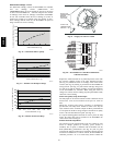
Outdoor Air Enthalphy Sensor/Enthalpy Controller
(HH57AC077)
To wire the outdoor air entha lpy sensor, perform the f ollowing (See
Fig. 25 and 26):
NOTE: The outdoor air sensor can be removed from the back of
the enthalpy controller and mounted remotely.
50HE,HJ