


59
with a Cycle-LOC protection device. The unit shuts down on
any safety trip and remains off; an indicator light on the
thermostat comes on. Check the reason for the safety trip.
Compressor restart is accomplished by manual reset at the
thermostat by turning the selector switch to OFF position and
then to ON position.
Step 10 —Heating
To start unit, turn on main power supply.
Set system selector switch at H EAT position and set thermostat at
a setting above room temperature. Set fan at AUTO position.
First stage of thermostat energizes the f irst--stage electric heater
elements; second stage energizes second--stage electric heater
elements, if installed. Check heating effects at air supply grille(s).
If electric heaters do not energize, reset limit switch (located on
evaporator--fan scroll) by pressing button located between
terminals on the switch.
TO SHUT OFF UNIT -- Set system selector switch at OFF
position. Resetting thermostat at a position below room
temperature temporarily shuts unit of f until space temperature
falls below thermostat setting.
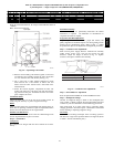
Step 11 —Safety Relief
A soft solder joint at the suction line fitting provides pressure
relief under abnormal temperature and pressure conditions.
Step 12 —Ventila tion (Continuous Fan)
Set fan and system selector switches at ON and OFF positions,
respectively. Evaporator fan operates continuously to provide
constant air circulation.
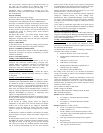
Step 13 —Operating Sequence
Cooling -- Units Without
Economizer
When thermostat calls for cooling, terminals G and Y1 are
energized. The indoor-fan contactor (IFC), reversing valve
solenoid (RVS) and compressor contactor are energized and
indoor-fan motor, compressor, and outdoor fan starts. The
outdoor fan motor runs continuously while unit is cooling.
Heating -- Units Without
Economizer
When the thermostat calls for heating, terminal W1 will be
energized with 24v. The IFC and heater contactor no. 1 (HC1)
are energized.
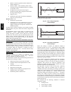
Cooling -- Units With Economi$er
IV
When free cooling is not available, the compressors will be
controlled by the zone thermostat. When free cooling is available,
the outdoor-air damper is modulated by the EconoMi$er IV
control to provide a 50_ to 55_F supply-air temperature into the
zone. As the supply-air temperature fluctuates above 55_ or
below 50_F, the dampers will be modulated (open or close) to
bring the supply-air temperature back within the set point limits.
Integrated EconoMi$er IV operation on single-stage units
requires a 2-stage thermostat (Y1 and Y2).
For EconoMi$er IV operation, there must be a thermostat call for
the fan (G). This will move the damper to its minimum position
during the occupied mode.
If the increase in cooling capacity causes the supply--air
temperature to drop below 45_F, then the outdoor--air damper
position will be fully closed. If the supply --air temperature
continues to fall, the outdoor--air damper will close. Control
returns to normal once the supply--air temperature rises above
48_F.
If optional power exhaust is installed, as the outdoor--air damper
opens and closes, the power exhaust fans will be energized and
deenergized.
If field--installed accessory CO
2
sensors are connected to the
EconoMi$er IV control, a demand controlled ventilation strategy
will begin to operate. As the CO
2
level in the zone increases
above the CO
2
set point, the minimum position of the damper
will be increased proportionally. As the CO
2
level decreases
because of the increase in fresh air, the outdoor--air damper will
be proportionally closed. Damper position will follow the h igher
demand condition from DCV mode or free cooling mode.
Damper movement from full closed to full open (or vice versa)
will take between 1--1/2 and 2--1/2 minutes.
If free cooling can be used as determined from the appropriate
changeover command (switch, dry bulb, enthalpy curve,
differential dry bulb, or differential enthalpy), a call for cooling
(Y1 closes at the thermostat) will cause the control to modulate
the dampers open to maintain the supply air temperature set point
at 50_ to 55_ F.
As the supply air temperature drops below the set point range of
50_ to 55_ F, the control will modulate the outdoor--air dampers
closed to maintain the proper supply--air temperature.
Heating -- Units With Economi$er
IV
When the room temperature calls for heat, the heating c ontrols are
energized as described in the Heating, Units Without Economizer
section. When the thermostat is satisfied, the economizer damper
moves to the minimum position.
Cooling -- Units W ith Economi$er2, Premierlink
t Control
and a
Thermostat
When free cooling is not available, the compressors will be
controlled by the PremierLink control in response to the Y1 and
Y2 inputs from the thermostat.
The PremierLink control will use the following information to
determine if free cooling is available:
S Indoor fan has been on for at least 30 seconds.
S The SPT, SAT, and OAT inputs must have valid
readings.
S OAT must be less than 75_F.
S OAT must be less than SPT.
S Enthalpy must be LOW (may be jumpered if an
enthalpy sensor not available).
S Economizer position is NOT forced.
Pre-cooling occurs when there is no call from the thermostat
except G. Pre-cooling is defined as the economizer modulates to
provide 70_F supply air.
When free cooling is available the PremierLink control will
control the compressors and economizer to provide a supply-air
temperature determined to meet the Y1 and Y2 calls from the
thermostat using the following three r outines. The three control
routines are based on OAT.
The 3 routines are based on OAT where:
SASP = Supply Air Set Point
DXCTLO = Direct Expansion Cooling Lockout Set Point
PID = Proportional Integral
Routine 1 (OAT < DXCTLO)
S Y1 energized – economizer maintains a SASP =
(SATLO1 + 3).
S Y2 energized – economizer maintains a SASP =
(SATLO2 + 3).
Routine 2 (DXCTLO<OAT<68_F)
S If only Y1 energized, the economizer maintains a
SASP = (SATLO1 + 3).
S If SAT > SASP + 5 and economizer position > 80%,
economizer will go to minimum position for 3 minutes
or until SAT > 68_F.
S First s tage of mechanical cooling will be energized.
S Integrator resets.
S Economizer opens again and controls to current SASP
after stage one on for 90 seconds.
50HE,HJ