


63
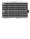
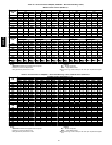
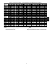
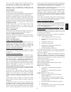
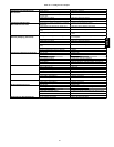
Table 35—Humidi-Mizer Adaptive Dehumidification System Sequence of Operation and
System Response — Single Compressor Unit (50HE003--006, 50HJ004-007)
THERMOSTAT INPUT ECONOMIZER FUNCTION 48HE, HJ UNIT OPERATION
H Y1 Y2 OAT. < Economizer Set Point Economizer Comp. 1 Subcooling Mode Hot Gas Reheat Mode
Off — —
Normal Operation
On On On No Off On Yes No
On On Off No Off On Yes No
On On On Yes On On Yes No
On On Off Yes On On No Yes
On Off Off No Off On No Yes
NOTE: O n a thermostat call for W1, all cooling and dehumidification will be off.
LEGEND
OAT --- Outdoor Ai r Temperature
C06046
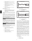
Fig. 56 --- Separating Coil Sections
4. Remove device holding coil sections together at return end
of condenser coil. Carefully separate the outer coil section
3 to 4 in. from the inner coil section. (See Fig. 57.)
5. Use a water hose or other suitable equipment to flush
down between the 2 coil sections to remove dirt and
debris. Clean the outer surfaces with a s tiff brush in the
normal manner.
6. Secure the sections together . Reposition t he outer coil
section and remove the coil corner post from between the
top panel and center post. Install t he coil corner and center
posts. Replace all screws.
Condensate
Drain
Check and clean each year at the start of the cooling season. In
winter, keep the drain dry or protect it against freeze-up.
Filters
Clean or replace at the start of each heating and cooling season, or
more often if operating conditions require it. Replacement filters
must be the same dimensions as the original filters.
Outdoor--Air Inlet Scr
een
Clean the screen with steam or hot water and a mild detergent. Do
not use disposable filters in place of screens.
Step 2 —Lubrication
Compr
essor
The compressor is charged with the correct amount of oil at the
factory.
Fan Motor
Bearings
Fan motor bearings are permanently lubricated. No further
lubrication is required. No lubrication of condense r-fan or
evaporator-fan m ot ors is required.
Evaporator Fan Belt
Adjustment
Inspect evaporator fan belt for wear, proper belt t ension, and
pulley alignment as conditions require or at the beginning of each
heating and air conditioning season. Refer to Step 7 -- Adjust
Evaporator Fan Speed for adjustment and alignment procedures.
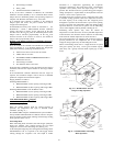
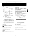
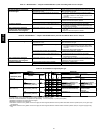
Step 3 —Condenser --Fan Adjustment
Shut off unit power supply. Remove condenser-fan assembly
(grille, motor, motor cover, and f an) and loosen fan hub
setscrews. Adjust fan height as shown in Fig. 57. Tighten
setscrews and replace condenser-fan assembly.
UNIT FAN HEIGHT (in.) — “A”
003-006 AND 007 (208/230 v) 2.75
007 (460 v) 3.50
C06138
Fig. 57 --- Condenser--Fan Adjustment
Step 4 —EconoMi$er IV Adjustment
Refer to Optional EconoMi$er IV and EconoMi$er2 section.
Step 5 —Refrigerant Charge
Amount of refrigerant charge is listed on unit nameplate (also
refer to Table 1). Refer to HVAC Servicing Procedures literature
available at your local distributor and the following procedures.
Unit panels must be in place when unit is operating during
charging procedure. Unit must operate a minimum of 10 minutes
before checking or adjusting refrigerant charge.
No
Charge
Use s tandard evacuating techniques. After evacuating system to
500 microns, weigh in the specified amount of refrigerant. (Refer
to Table 1 and unit information plate.)
50HE,HJ