


35
NOTE: These instructions are for installing the optional
EconoMi$er IV and EconoMi$er2 only. Refer to the accessory
EconoMi$er IV or EconoMi$er2 installation instructions when
field installing an EconoMi$er IV or EconoMi$er2 accessory .
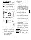
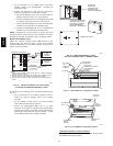
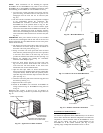
1. To remove the existing unit filter access panel, raise the
panel and swing the bottom outward. The panel is now
disengaged from the track and can be removed. (See
Fig. 29.)
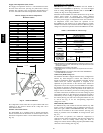
2. The box with the economizer hood components is shipped
in the compartment behind the economizer. The
EconoMi$er IV controller is mounted on top of the
EconoMi$er IV in the position shown in Fig. 24. The
optional EconoMi$er2 with 4 to 20 mA actuator signal
control does not include the EconoMi$er IV controller. To
remove the component box from its shipping position,
remove the screw holding the hood box bracket to the top
of the economizer. Slide the hood box out of the unit. (See
Fig. 30.)
IMPORTANT: If the power exhaust accessory is to be installed
on the unit, the hood shipped with the unit will not be used and
must be discarded. Save the aluminum filter for use in the power
exhaust hood assembly.
3. The indoor coil access panel will be used as the top of the
hood. Remove the screws along the sides and bottom of
the indoor coil access panel. (See Fig. 31.)
4. Swing out indoor coil access panel and insert the hood
sides under the panel (hood top). Use the screws provided
to attach the hood sides to the hood top. Use screws
provided to attach the hood sides to the unit. (See Fig. 32.)
5. Remove the shipping tape holding the economizer
barometric relief d amper in place.
6. Insert the hood divider between the hood sides. (See
Fig. 32 and 33.) Secure hood divider with 2 screws on
each hood side. The hood divider is also used as the
bottom filter rack for the aluminum filter.
7. Open the f ilter clips which are l ocated underneath the
hood top. Insert the aluminum filter into the bottom filter
rack (hood divider). Push the filter into position past the
open filter c lips. Close the filter clips to lock the filter into
place. (See Fig. 33.)
8. Caulk the ends of the joint between the unit top panel and
the hood top. (See Fig. 31.)
9. Replace the filter access panel.
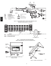
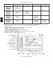
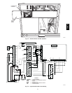
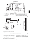
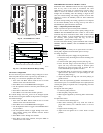
10. Install all EconoMi$er IV accessories. EconoMi$er IV
wiring is shown in Fig. 34. EconoMi$er2 wiring is shown
in Fig. 35.
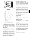
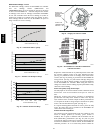
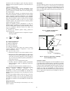
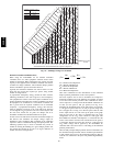
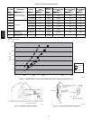
Barometric flow capacity is shown in Fig. 36. Outdoor air
leakage is shown in Fig. 37. Return air pressure drop is shown in
Fig. 38.
FILTER ACCESS PANEL
OUTDOOR-AIR OPENINGAND
INDOOR COILACCESS PANEL
COMPRESSOR
ACCESS PANEL
C06023
Fig. 29 --- Typical Access Panel Locations
H
o
o
d
B
o
x
HOOD BOX
BRACKET
C06024
Fig. 30 --- Hood Box Removal
SIDE
PANEL
INDOOR
COIL
ACCESS
PANEL
INDOOR
COIL
ACCESS
PANEL
CAULK
HERE
TOP
SIDE
PANEL
C06025
Fig. 31 --- Indoor Coil A ccess Panel Relocation
B
TOP
PANEL
INDOOR COIL
ACCESS PANEL
19 1/16”
SCREW
HOOD DIVIDER
LEFT
HOOD
SIDE
33 3/8”
C06026
Fig. 32 --- Outdoor--Air Hood Construction
Economi$er IV Standard
Sensors
Outdoor Air Temperature (OAT) Sensor
The outdoor a ir temperature sensor ( H H57A C074) i s a 1 0 t o 20 mA
device used to me asure the outdoor -a i r te m peratur e. The outdoor-a ir
temper ature is used to determine when the EconoMi$er IV can be
used f or fr ee cooling. The sensor is f actory-ins talled on the
EconoM i$e r IV in the outdoor air stream. (See Fig. 27.) T he
operating range of temper ature measurem ent is 4 0_ to 100_F.
50HE,HJ