


2
Step 1 —Provide Unit Support
Roof
Curb
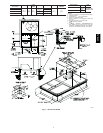
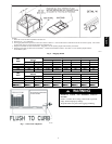
Assemble and install accessory roof curb in accordance with
instructions shipped with curb. (See Fig. 2.) Install insulation,
cant strips, roofing felt, and counter flashing as shown. Ductwork
must be attached to curb, not to the unit. If electric control power
or gas service is to be routed through the basepan, attach the
accessory thru-the-bottom service connections to the basepan in
accordance with the accessory installation instructions.
Connections must be installed before unit is set on roof curb.
C06108
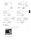
Fig. 1 --- Horizontal Conversion Panels
IMPORTANT: The gasketing of the unit t o the roof curb is critical
for a watertight seal. Install gasket supplied with the roof curb as
show n i n Fig. 2. I m pr operly applied gas ket can result in ai r leaks and
poor unit pe rformanc e.
Curb should be level. Unit leveling tolerances are shown in Fig.
3. This is necessary for unit drain to function properly. Refer to
Accessory Roof Curb Installation Instructions for additional
information as required.
Slab Mount (Horizontal Units Only)
Provide a level concrete slab that extends a minimum of 6 in.
beyond unit cabinet. Install a gravel apron in front of
condenser-coil air inlet to prevent grass and foliage from
obstructing airflow.
NOTE: Horizontal units may be installed on a roof curb if
required.
Alternate Unit
Support
When the curb or adapter cannot be used, support unit with
sleeper rails using unit curb or adapter support area. If sleeper
rails cannot be used, support the long sides of the unit with a
minimum of 3 equally spaced 4-in. x 4 -in. pads on each side.
Step 2 —Field Fabricate Ductwork
Secure all ducts to roof curb and building structure on vertical
discharge units. Do not connect ductwork to unit. For horizontal
applications, field-supplied isolation flanges should be attached to
horizontal discharge openings and all ductwork should be secured
to the flanges. Insulate and weatherproof all external ductwork,
joints, and roof openings with counter flashing and mastic in
accordance with applicable codes.
Ducts passing through an unconditioned space must be insulated
and covered with a vapor barrier.
If a plenum return is used on a vertical unit, the return should be
ducted through the roof deck to comply with applicable fire
codes.
A minimum clearance is not required around ductwork. Cabinet
return-air static pressure (a negative condition) shall not exceed
0.35 in. wg with economizer or 0.45 in. wg without economizer.
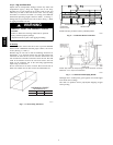
Step 3 —Install External Trap for
Condensate Drain
Condensate drain connections are located on the bottom and side
of the unit. Unit discharge connections do not determine the use
of drain connections; either drain connection can be used with
vertical or horizontal applications.
When using the standard side drain connection, ensure the plug
(Red) in the alternate bottom connection is tight before installing
the unit.
To use the bottom drain connection for a roof curb installation,
relocate the factory-installed plug (Red) from the bottom
connection to the side connection. The center drain plug looks
like a star connection, however it can be removed with a
1
/
2
-in.
socket drive extension. (See Fig. 4.) The piping for the
condensate drain and external trap can be completed after the unit
is in place.
All units must have an external trap for condensate drainage.
Install a trap 4-in. deep and protect against freeze-up. If drain line
is installed downstream from the external trap, pitch the line a way
from the unit at 1 in. per 10 ft of run. Do not use a pipe size
smaller than the unit connection (
3
/
4
in.). (See Fig. 5.)
50HE,HJ