


58
PRE-START-UP
FIRE, EXPLOSION, ELECTRICAL SHOCK HAZARD
Failure to foll ow this war ning could result in p ersonal
injur y, death, and/or proper t y damage .
1. Follow recognized safety practices and wea r protective
goggles whe n c hecking or servicing a refrigerant system.
2. Do not operate t he compr essor or provide any electric
powe r to the unit unless the com pressor ter minal cover is
in place and s ecured.
3. Do not rem ove the compress or ter m i nal cover until all
electrical sources are disconnected and ta gged w i th lockout
tags.
4. Rel ieve all pressure from the system be f ore touching or
disturbi ng anyt hing i nside t he te rminal box if a
refrige ra nt leak i s suspected a round the compre ssor
terminals. Use accepted methods to rec over the
refrigerant.
5. Never a ttempt t o r epair a soldered connection while the
refrige ra nt syst em is under pressure.
6. Do not use a torc h t o re m ove any com ponent. The
system contains oil and refrigerant under pr essure. To
remove a component , wea r pr ote ctive goggles a nd pr o ceed
as follows:
a. Shut off electrical power to the unit and tag
disconnect.
b. Recover refrigerant to relieve all pressure
from the system using both high-pressure
and low-pressure ports.
c. Cut component connection tubing with a
tubing cutter, and remove the component
from the unit.
d. Carefully unsweat the remaining tubing
stubs when necessary . Oil can ig nite when
exposed to a torch flame.
!
WARNING
Proceed as follows to inspect and prepare the unit for initial
start-up:
1. Remove all access panels.
2. Read and follow instructions on all WARNING,
CAUTION, and INFORMATION labels attached to, o r
shipped with, u nit.
3. Make the following inspections:
a. Inspect for s hipping and handling damages such as
broken lines, loose parts, or disconnected wires, etc.
b. Inspectforoilatallrefrigeranttubingconnectionsandon
unit base. Detecting oil generally indicates a refrigerant
leak. Leak-test all refrigerant tubing connections using
electronic leak detector, halide torch, or liquid-soap
solution.
c. Inspect all field-wiring and factory-wiring connections.
Besurethatconnectionsarecompleted andtight.Besure
that wires are not in contact with refrigerant tubing or
sharp e dges.
d. Inspect coil fins. If damaged during shipping and
handling, carefully straighten fins with a fin comb.
4. Verify the following conditions:
a. Make sure that condenser-fan blade are correctly
positionedinfanorifice.SeeCondenser-FanAdjustment
section f or more details.
b. Make sure that air filter(s) is in p lace.
c. Make sure that condensate drain trap is filled with water
to ensure proper drainage.
d. Make sure that all tools and miscellaneous loose parts
have been removed.
START-UP
Step 1 —Unit Preparation
Make sure that the unit has been installed in accordance with
installation instructions and applicable codes.
Step 2 —Return--Air Filters
Make sure the correct filters are installed in the unit (See Table 1).
Do not operate the unit without return-air filters.
Step 3 —Outdoor--Air I nlet Screens
Outdoor-air inlet screen(s) must be in place before operating the
unit.
Step 4 —Compressor Mounting
Compressors are internally spring mounted. Do not loosen or
remove the compressor holddown bolts.
Step 5 —Internal Wiring
Check all electrical connections in unit control boxes; tighten
them as required.
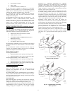
Step 6 —Refrigerant Service Ports
Each unit system has 4 Schrader--type service ports: one on the
suction line, one on the liquid line, and 2 on the compressor
discharge line. Be sure that caps on the ports are tight.
Step 7 —High Flow Valv es
Two high flow refrigerant valves are located on the hot gas tube
coming out of the compressor and the suction tubes. Large black
plastic caps distinguish these valves with O--rings located inside
the caps. No field access to these valves is available a t this time.
Ensure the plastic caps are in place and tight or the possibility of
refrigerant leakage could occur.
Step 8 —Compressor Rotation
On 3-phase units be certain that the compressor is rotating in the
proper direction. To determine whether or not compressor is
rotating in the proper direction:
1. Connect the service gauges to suction and discharge
pressure fittings.
2. Energize the compressor.
3. The suction pressure should drop and the discharge
pressure should rise, as is normal on any start-up.
If the suction pressure does not drop and the discharge pressure
does not rise to normal levels:
1. Note that the indoor fan (006 and 007 three-phase units
only) is probably also rotating in the wrong direction.
2. Turn off power to the unit and tag disconnect.
3. Reverse any two of the unit power leads.
4. Turn on power to the unit and energize the compressor.
The suction and discharge pressure levels should now move to
their normal start-up levels.
NOTE: When the compressor is rotating in the wrong direction,
the unit makes more noise and does not provide cooling.
Step 9 —Cooling
Set the space thermostat to the OFF position. Set the system
selector switch at COOL position and the fan switch at AUTO
position. Adjust the thermostat to a setting below room
temperature. The compressor starts when contactor closes.
Check cooling effects at a setting below room temperature.
Check the unit charg e. Refer to Refrigerant Charge section.
Reset the thermostat at a position above room temperature. The
compressor will shut off.
To Shut Off Unit -- Set the system selector switch at OFF
position. Resetting the thermostat at a position above room
temperature shuts off the unit temporarily until the space
temperature exceeds the thermostat setting. Units are equipped
50HE,HJ