


40
CONTROL
CURVE
A
B
C
D
CONTROL POINT
APPROX.
deg. F (deg. C)
AT 50% RH
73 (23)
70 (21)
67 (19)
63 (17)
1
2
1
4
1
6
1
8
2
0
2
2
2
4
26
28
30
32
3
4
3
6
3
8
40
42
4
4
46
9
0
1
0
0
80
70
6
0
50
4
0
30
20
1
0
ENTHALPY BTU PER POUND DRY AIR
85
(29)
90
(32)
95
(35)
100
(38)
105
(41)
110
(43)
35
(2)
35
(2)
40
(4)
40
(4)
105
(41)
110
(43)
45
(7)
45
(7)
50
(10)
50
(10)
55
(13)
55
(13)
60
(16)
60
(16)
65
(18)
65
(18)
70
(21)
70
(21)
75
(24)
75
(24)
80
(27)
80
(27)
85
(29)
90
(32)
95
(35)
100
(38)
A
A
B
B
C
C
D
D
RELATIVE HUMIDITY (%)
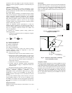
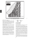
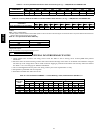
HIGH LIMIT
CURVE
APPROXIMATE DRY BULB TEMPERATURE--degrees F (degrees C)
C06037
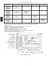
Fig. 43 --- Enthalpy Changeover Set Points
Demand Controlled Ventilation (DCV)
When using the EconoMi$er IV for demand controlled
ventilation, there are some equipment selection criteria which
should be considered. When selecting the heat capacity and cool
capacity of the equipment, the maximum ventilation rate must be
evaluated for design conditions. The maximum damper position
must be calculated to provide the desired fresh air.
Typically the maximum ventilation rate will be about 5 to 10%
more than the typical cfm required per person, using normal
outside air design criteria.
A proportional anticipatory strategy should be taken with the
following conditions: a zone with a large area, varied occupancy,
and equipment that cannot exceed the required ventilation rate at
design conditions. Exceeding the required ventilation rate means
the equipment can condition air at a maximum ventilation rate
that is greater than the required ventilation rate f or maximum
occupancy. A proportional-anticipatory strategy will cause the
fresh air supplied to increase as the room CO
2
level increases
even though the CO
2
set point has not been reached. By the time
the CO
2
level reaches the set point, the damper will be at
maximum ventilation and should maintain the set point.
In order to have the CO
2
sensor control the economizer damper in
this manner, first determine the damper voltage output for
minimum or base ventilation. Base ventilation is the ventilation
required to remove contaminants during unoccupied periods. The
following equation may be used to determine the percent of
outside-air entering the building for a given damper position. For
best results there should be at least a 10 degree difference in
outside and return-air temperatures.
(T
Ox
OA
)
+(TR
x
RA
)=T
M
100 100
T
O
= Outdoor-Air Temperature
OA = Percent of Outdoor A ir
T
R
= Re turn-Air Te m per ature
RA = Percent of Return Air
T
M
= Mixed-Air T emperature
Once base ventilation has been determined, set the minimum
damper p osition potentiometer to the correct position.
The same equation can be used to determine the occupied or
maximum ventilation r ate to the building. For example, an output
of 3.6 volts to the actuator provides a base ve ntilation rate of 5%
and an output of 6.7 volts provides the maximum ventilation r ate
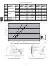
of 20% (or base plus 15 cfm per person). Use Fig. 42 to
determine the maximum setting of the CO
2
sensor. For example,
a 1100 ppm set point relates to a 15 cfm per person design. Use
the 1100 ppm curve on Fig. 45 to find the point when the CO
2
sensor output will be 6.7 volts. Line up the point on the graph
with the left side of the chart to determine that the range
configuration for the CO
2
sensor should be 1800 ppm. The
EconoMi$er IV controller will output the 6.7 volts from the CO
2
sensor to the actuator when the CO
2
concentration i n the space is
at 1100 ppm. The DCV set point may be left at 2 volts since the
CO
2
sensor voltage will be ignored by the EconoMi$er IV
controller until it rises above the 3.6 volt setting of the minimum
position potentiometer.
Once the fully occupied damper position has been determined, set
the maximum damper demand control ventilation potentiometer
to this position. Do not set to the maximum position as this can
result in over-ventilation t o the space and potential high-humidity
levels.
50HE,HJ