


41
TR1
24 Vac
COM
TR
24
Vac
HOT
12
3
4
5
EF
EF1
+
_
P1
T1
P
T
N
EXH
2V 10V
EXH
Set
Set
2V 10V
2V 10V
DCV
DCV
Free
Cool
B
C
A
D
SO+
SR+
SR
SO
AQ1
AQ
DCV
Min
Pos
Open
Max
N1
C06038
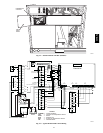
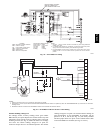
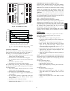
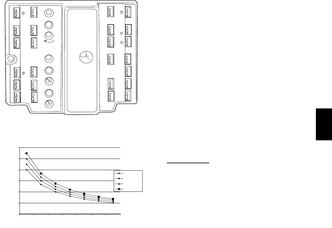
Fig. 44 --- EconoMi$er IV Control
0
1000
2000
3000
4000
5000
6000
2345678
800 ppm
900 ppm
1000 ppm
1100 ppm
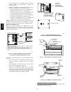
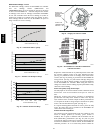
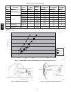
RANGE CONFIGURATION (ppm)
DAMPER VOLTAGE FOR MAX VENTILATION RATE
CO SENSOR MAX RANGE SETTING
2
C06039
Fig. 45 --- CO
2
Sensor Maximum Range Setting
CO
2
Sensor Configuration
The CO
2
sensor has preset standard voltage settings that can be
selected anytime after the sensor is powered u p. (See Table 8.)
Use setting 1 or 2 for Carrier equipment. (See Table 8.)
1. Press Clear and Mode buttons. Hold at least 5 seconds
until the sensor enters the Edit mode.
2. Press Mode twice. The STDSET Menu will appear.
3. Use the Up/Down button to select the preset number. (See
Table 8.)
4. Press Enter to lock in the selection.
5. Press Mode to exit and resume normal operation.
The custom settings of the CO
2
sensor can be changed anytime
after the sensor is ener gized. Follow the steps below to change the
non-standard settings:
1. Press Clear and Mode buttons. Hold at least 5 seconds
until the sensor enters the Edit mode.
2. Press Mode twice. The STDSET Menu will appear.
3. Use the Up/Down button to toggle to the NONSTD menu
and press Enter.
4. Use the Up/Down button to toggle through each of the
nine variables, starting with Altitude, until the desired
setting i s reached.
5. Press Mode to move through the variables.
6. Press Enter to lock in the selection, then press Mode to
continue to the next variable.
Dehumidification of Fresh Air with DCV Control
Information from ASHRAE indicates that the largest humidity
load on any zone is the fresh air introduced. For some
applications, a device such as a 62AQ energy recovery unit is
added to reduce the moisture content of the fresh air being
brought into the building when the enthalpy is high. In most
cases, the normal heating and cooling processes are more than
adequate to remove the humidity loads for most commercial
applications.
If normal rooftop heating and cooling operation is not adequate
for the outdoor humidity level, an energy recovery unit and/or a
dehumidification option should be considered.
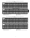
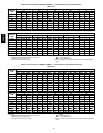
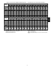
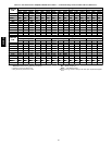
Step 7 —Adjust Evaporator--Fan Speed
Adjust evaporator-fan speed to meet jobsite conditions.
Tables 9 and 10 show fan rpm at motor pulley settings for the
50HE003--006 and 50HJ004--007 units. Tables 11 and 14 show
maximum amp draw of belt-drive motor. Table 13 shows sound
data. Refer to Tables 15-34 for performance data. See Table 35
for accessory static pressure drop. See Fig. 47 for the
Humidi-MiZer system static pressure drops.
For units with electric heating, required minimum cfm is 900 for
50HJ004; 1200 for 50HJ005; 1500 for 50HJ006 and 1800 for
50HJ007.
Belt Drive
Motors
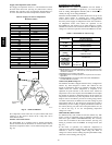
Fan motor pulleys are factory set for speed shown in Table 1.
Check pulley alignment and belt tension prior to start-up.
To change fan speed:
1. Shut off the unit power supply and tag disconnect.
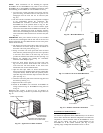
2. Loosen the belt by loosening the fan motor mounting nuts.
(See Fig. 47.)
3. Loosen movable pulley flange setscrew (See Fig. 48).
4. Screw movable flange toward fixed flange to increase
speed and away from fixed flange to decrease speed.
Increasing fan speed increases load on motor. Do not
exceed maximum speed specified in Ta ble 1.
5. Set movable flange at nearest keyway of pulley hub and
tighten setscrew. (See Table 1 for speed change for each
full turn of pulley f lange.)
6. Adjust belt tension and align fan and motor pulleys per
guidance below.
NOTE: Once the required flange position is d etermined f or the
correct blower rpm, it is recommended (but not required) that the
variable pitch pulley be replaced with a corresponding size fixed
sheave pulley .
To align fan and motor pulleys:
1. Loosen fan pulley setscrews.
2. Slide fan pulley along fan shaft.
3. Make angular alignment by loosening motor from mount-
ing.
To adjust belt tension:
1. Loosen fan motor mounting nuts.
2. Slide motor mounting plate away from fan scroll for
proper belt tension (
1
/
2
-in.deflectionwith7to10lbof
force).
3. Tighten motor mounting nuts.
4. Adjust bolt and tighten nut to secure motor in fixed
position.
50HE,HJ