


70
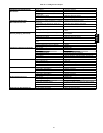
Table 37—Humidi-MiZer Adaptive Dehumidification System Subcooling Mode Service Analysis
PROBLEM CAUSE REMEDY
Subcooling Mode (Liquid Reheat)
Will Not Energize.
No power to control transformer from
evaporator- fan motor.
Check power source and evaporator-fan relay. Ensure all
wire connectionsare tight.
No power from control transformer to liquid line
solenoid valve.
1. Fuse open; check fuse. Ensure continuity of wiring.
2. Low-pressure switch open. Cycle unit off and allow
low-pressure switch to reset. Replace switch if it will
not close.
3. Transformer bad; check transformer.
Liquid line solenoid valve will not operate. 1. Solenoid coil defective; replace.
2. Solenoid valve stuck open; replace.
Liquid line solenoid valve will not open. Valve is stuck cl osed; replace valve.
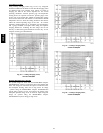
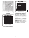
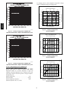
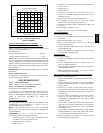
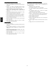
Low System Capacity. Low refrigerant charge or frosted evaporator coil. 1. Check cha rge amount. Charge per Fig. 59-62.
2. Evaporator coil frosted; check and replace low-pres-
sure switch if necessary.
Loss of Compressor Superheat
Conditions with Subcooling/Reheat
Dehumidification Coil Energized.
Thermostatic expansion valve (TXV). 1. CheckTXV bulb mounting, and secure tightly to suc-
tion line.
2. Replace TXV if stuck open or closed.
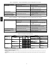
Table 38—Humidi-MiZer Adaptive Dehumidification System Hot Gas Reheat Mode Service Analysis
PROBLEM CAUSE REMEDY
Reheat Mode Will Not Energize. No power to control transformer from
evaporator- fan motor.
Check power source and evaporator-fan relay. Ensure all
wire connectionsare tight.
No power from control transformer to hot gas
line solenoid valve
1. Fuse open; check fuse. Ensure continuity of wiring.
2. Low-pressure switch open. Cycle unit off and allow
low-pressure switch to reset. Replace switch if it will
not close.
3. Transformer bad; check transformer.
Hot gas line solenoid valve will not operate. 1. Solenoid coil defective; replace.
2. Solenoid valve stuck closed; replace.
Low refrigerant charge or frosted evaporator coil. 1. Check cha rge amount. Charge per Fig. 59-62.
2. Evaporator coil frosted; check and replace low-pres-
sure switch if necessary.
Loss of Compressor Superheat
Conditions with Subcooling/Reheat
Dehumidification Coil Energized.
Thermostatic expansion valve (TXV). 1. CheckTXV bulb mounting, and secure tightly to suc-
tion line.
2. Replace TXV if stuck open or closed.
Excessive Superheat. Liquid line solenoid valve will n ot operate. Valve is stuck, replace valve.
Hot gas line solenoid valve will not close. Valve is stuck; replace valve.
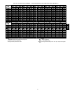
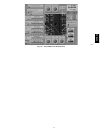
Table 39—EconoMi$er IV Input/Output Logic
INPUTS OUTPUTS
Demand Control
Ventilation (DCV)
Enthalpy*
Y1 Y2
Compressor NTerminal†
Outdoor Return
Stage
1
Stage
2
Occupied Unoccupied
Damper
Below set
(DCV LED O ff)
High
(F ree Cooling LED Off)
Low On On On On Minimum position Closed
On Off On Off
Off Off Off Off
Low
(F ree Cooling LED On)
High On On On Off Modulating** (between min.
position and full-open)
Modulating** (between
closed and full-open)
On Off Off Off
Off Off Off Off Minimum position Closed
Above set
(DCV LED On)
High
(F ree Cooling LED Off)
Low On On On On Modulating†† (between min.
position and DCV maximum)
Modulating†† (between
closed and DCV
maximum)
On Off On Off
Off Off Off Off
Low
(F ree Cooling LED On)
High On On On Off Modulating*** Modulating†††
On Off Off Off
Off Off Off Off
*For single enthalpy control,themodulecomparesoutdoorenthalpyto theABCDsetpoint.
†Power at N terminal determines Occupied/Unoccupied setting: 24 vac (Occupied), no power (Unoccupied).
**Modulation is based on th e supply-air sensor signal.
††Modulation is based on the DCV signal.
***Modulation is basedon the greater of DCV and supply-air sensor signals, between minimum position and either maximum position (DCV) or fully open (sup-
ply-air si gnal).
†††Modulation is basedon the greater of DCV and supply-air sensor signals, between closed and either maximum position (DCV) or fully open (supply-airsig-
nal).
50HE,HJ