


9
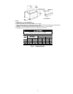
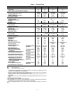
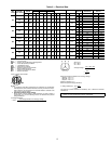
Table 1 — Physical Data
LEGEND
*The ZRU140KC compressor is a tandem compressor, consisting of a ZR72KC (25% total
capacity) and a ZR68KC (24% total capacity).
†Circuit 1 uses the lower portion of the condenser coil and lower portion of the evaporator
coils; and Circuit 2 uses the upper portion of both coils.
**Pulley has 6 turns. Due to belt and pulley size, movable pulley cannot be set to 0 to 1
1
/
2
turns open.
††Pulley has 6 turns. Due to belt and pulley size, movable pulley cannot be set to 0 to
1
/
2
turns
open.
***Rollout switch is manual reset.
†††A Liquid Propane kit is available as an accessory.
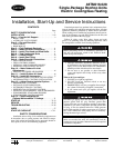
¶The 48TM028 unit requires 2-in. industrial-grade filters capable of handling face velocities up
to 625 ft/min (such as American Air Filter no. 5700 or equivalent).
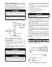
NOTE: The 48TM016-028 units have a low-pressure switch (standard) located on the suction
side.
UNIT 48TM 016D/F 020D/F 025D/F 028D/F
NOMINAL CAPACITY (tons) 15 18 20 25
OPERATING WEIGHT 1800 1850 1900 2270
Economizer 90 90 90 90
MoistureMi$er™ Dehumidification Package 40 40 40 40
COMPRESSOR/MANUFACTURER Scroll, Copeland
Quantity...Model (Ckt 1, Ckt 2)
1...ZR94KC,
1...ZR72KC
1...ZR108KC,
1...ZR94KC
1...ZR125KC,
1...ZR108KC
1...ZRU140KC,*
1...ZR144KC
Capacity Stages (%) 60, 40 55, 45 55, 45 50, 50
Number of Refrigerant Circuits 22 2 2
Oil (oz) (Ckt 1, Ckt 2) 85, 60 106, 81 106,106 136, 106
REFRIGERANT TYPE R-22
Expansion Device TXV
Operating Charge (lb-oz)
Circuit 1† 19-8 19-8 19-11 26-13
Circuit 2 13-8 19-2 13-14 25-10
CONDENSER COIL Cross-Hatched
3
/
8
-in. Copper Tubes, Aluminum Lanced,
Aluminum Pre-Coated, or Copper Plate Fins
Rows...Fins/in. 4...15 4...15 4...15 3...15 (2 coils)
Total Face Area (sq ft) 21.7 21.7 21.7 43.4
CONDENSER FAN Propeller Type
Nominal Cfm 10,500 10,500 14,200 21,000
Quantity...Diameter (in.) 3...22 3...22 2...30 6...22
Motor Hp...Rpm
1
/
2
...1050
1
/
2
...1050 1...1075
1
/
2
...1050
Watts Input (Total) 1100 1100 3400 2200
EVAPORATOR COIL Cross-Hatched
3
/
8
-in. Copper Tubes, Aluminum Lanced or
Copper Plate Fins, Face Split
Rows...Fins/in. 4...15 4...15 4...15 4...15
Total Face Area (sq ft) 17.5 17.5 17.5 17.5
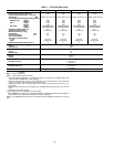
EVAPORATOR FAN Centrifugal Type
Quantity...Size (in.) 2...12 x 12 2...12 x 12 2...12 x 12 2...12 x 12
Type Drive Belt Belt Belt Belt
Nominal Cfm 6000 7200 8000 10,000
Motor Hp 55 7.5 10
Motor Nominal Rpm 1745 1745 1745 1740
Maximum Continuous Bhp 6.13 5.90
8.7 [208/230, 575 v]
9.5 [460 v]
10.2 [208/230, 575 v]
11.8 [460 v]
Motor Frame Size 184T 184T 213T 215T
Nominal Rpm High/Low —— — —
Fan Rpm Range Low-Medium Static 873-1021 910-1095 1002-1151 1066-1283
High Static 1025-1200 1069-1287 1193-1369 1332-1550
Motor Bearing Type Ball Ball Ball Ball
Maximum Allowable Rpm 1550 1550 1550 1550
Motor Pulley Pitch Diameter Low-Medium Static 4.9/5.9 4.9/5.9 5.4/6.6 4.9/5.9
Min/Max (in.) High Static 4.9/5.9 4.9/5.9 5.4/6.6 4.9/5.9
Nominal Motor Shaft Diameter (in.) 1
1
/
8
1
1
/
8
1
3
/
8
1
3
/
8
Fan Pulley Pitch Diameter (in.) Low-Medium Static 9.4 9.4 9.4 8.0
High Static 8.0 8.0 7.9 6.4
Nominal Fan Shaft Diameter (in.) 1
7
/
16
1
7
/
16
1
7
/
16
1
7
/
16
Belt, Quantity...Type...Length (in.) Low-Medium Static 1...BX...50 1...BX...50 1...BX...53 2...BX...50
High Static 1...BX...48 1...BX...48 1...BX...50 2...BX...47
Pulley Center Line Distance (in.) 13.3-14.8 13.3-14.8 14.6-15.4 14.6-15.4
Speed Change per Full Turn of
Movable Pulley Flange (rpm)
Low-Medium Static 37 37 37 36
High Static 44 34 44 45
Movable Pulley Maximum Full Turns
From Closed Position 6** 6†† 6** 6††
Factory Speed 3.5 3.5 3.5 3.5
Factory Speed Setting (rpm) Low-Medium Static 965 1002 1120 1182
High Static 1134 1178 1328 1470
Fan Shaft Diameter at Pulley (in.) 1
7
/
16
1
7
/
16
1
7
/
16
1
7
/
16
Bhp — Brake Horsepower
TXV — Thermostatic Expansion Valve