


45
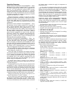
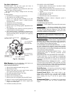
Belt Tension Adjustment — To adjust belt tension:
1. Loosen fan motor bolts.
2. Turn motor jacking bolt to move motor mounting plate up
or down for proper belt tension (
3
/
8
in. deflection at
midspan with one finger [9 lb force]).
3. Tighten nuts.
4. Adjust bolts and nut on mounting plate to secure motor in
fixed position.
Condenser-Fan Adjustment
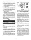
48TM016,020,028 UNITS (Fig. 52)
1. Shut off unit power supply.
2. Remove access panel(s) closest to the fan to be adjusted.
3. Loosen fan hub setscrews.
4. Adjust fan height on shaft using a straightedge placed
across the fan orifice.
5. Tighten setscrews and replace panel(s).
6. Turn on unit power.
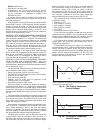
48TM025 UNITS (Fig. 53)
1. Shut off unit power supply.
2. Remove fan top-grille assembly and loosen fan hub
screws.
3. Adjust fan height on unit, using a straightedge placed
across the fan orifice.
4. Tighten setscrews and replace rubber hubcap to prevent
hub from rusting to motor shaft.
5. Fill hub recess with permagum if rubber hubcap is
missing.
Power Failure — Dampers have a spring return. In event
of power failure, dampers will return to fully closed position
until power is restored. Do not manually operate economizer
motor.
Refrigerant Charge — Amount of refrigerant charge is
listed on unit nameplate and in Table 1. Refer to Carrier GTAC
II; Module 5; Charging, Recovery, Recycling, and Reclama-
tion section for charging methods and procedures. Unit
panels must be in place when unit is operating during charging
procedure.
NOTE: Do not use recycled refrigerant as it may contain
contaminants.
NO CHARGE — Use standard evacuating techniques. After
evacuating system, weigh in the specified amount of refriger-
ant (refer to Table 1).
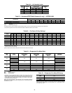
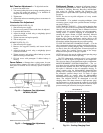
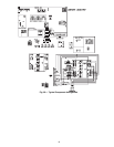
LOW CHARGE COOLING — Using cooling charging chart
(see Fig. 54), add or remove refrigerant until conditions of the
chart are met. Note that charging chart is different from those
normally used. An accurate pressure gage and temperature-
sensing device is required. Charging is accomplished by
ensuring the proper amount of liquid subcooling. Measure
liquid line pressure at the liquid line service valve using
pressure gage. Connect temperature sensing device to the
liquid line near the liquid line service valve and insulate it so
that outdoor ambient temperature does not affect reading.
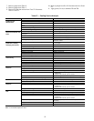
TO USE THE COOLING CHARGING CHART — Use the
above temperature and pressure readings, and find the intersec-
tion point on the cooling charging chart. If intersection point
on chart is above line, add refrigerant. If intersection point on
chart is below line, carefully recover some of the charge.
Recheck suction pressure as charge is adjusted.
NOTE: Indoor-air cfm must be within normal operating range
of unit. All outdoor fans must be operating.
The TXV (thermostatic expansion valve) is set to maintain
between 15 and 20 degrees of superheat at the compressors.
The valves are factory set and should not require re-adjustment.
MOISTUREMI$ER™ SYSTEM CHARGING — The sys-
tem charge for units with the MoistureMi$er option is greater
than that of the standard unit alone. The charge for units with
this option is indicated on the unit nameplate drawing. To
charge systems using the MoistureMi$er dehumidification
package, fully evacuate, recover, and re-charge the system to
the nameplate specified charge level. To check or adjust
refrigerant charge on systems using the MoistureMi$er
dehumidification package, charge per the standard subcooling
charts. The subcooler MUST be deenergized to use the
charging charts. The charts reference a liquid pressure (psig)
and temperature at a point between the condenser coil and the
subcooler coil. A tap is provided on the unit to measure liquid
pressure entering the subcooler (leaving the condenser).
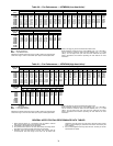
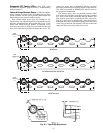
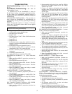
NOTE: Dimensions are in inches.
Fig. 53 — Condenser-Fan Adjustment,
48TM025
NOTE: Dimensions are in inches.
Fig. 52 — Condenser Fan Adjustment,
48TM016,020,028
50
40
100
150
200
250
300
350
400
60
80
100
120
140
ALLOUTDOOR FANS MUSTBE OPERATING
LIQUID PRESSUREATLIQUID VALVE (PSIG)
LIQUID TEMPERATUREAT LIQUID VALVE (DEG F)
BOTH CIRCUITS
REDUCE CHARGE IF BELOW CURVE
ADD CHARGE IFABOVE CURVE
Fig. 54 — Cooling Charging Chart