


28
Outdoor Enthalpy Changeover
— For enthalpy control, ac-
cessory enthalpy sensor (part number HH57AC078) is
required. Replace the standard outdoor dry bulb temperature
sensor with the accessory enthalpy sensor in the same mount-
ing location. See Fig. 33. When the outdoor air enthalpy rises
above the outdoor enthalpy changeover set point, the outdoor-
air damper moves to its minimum position. The outdoor
enthalpy changeover set point is set with the outdoor enthalpy
set point potentiometer on the EconoMi$erIV controller. The
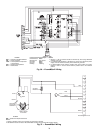
set points are A, B, C, and D. See Fig. 41. The factory-installed
620-ohm jumper must be in place across terminals SR and SR+
on the EconoMi$erIV controller. See Fig. 33 and 42.
Differential Enthalpy Control
— For differential enthalpy
control, the EconoMi$erIV controller uses two enthalpy sen-
sors (HH57AC078 and CRENTDIF004A00), one in the out-
side air and one in the return airstream or the EconoMi$erIV
frame. The EconoMi$erIV controller compares the outdoor air
enthalpy to the return air enthalpy to determine EconoMi$erIV
use. The controller selects the lower enthalpy air (return or out-
door) for cooling. For example, when the outdoor air has a low-
er enthalpy than the return air and is below the set point, the
EconoMi$erIV opens to bring in outdoor air for free cooling.
Replace the standard outside air dry bulb temperature sen-
sor with the accessory enthalpy sensor in the same mounting
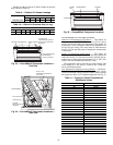
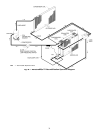
location. See Fig. 33. Mount the return air enthalpy sensor in
the return airstream. See Fig. 40. The outdoor enthalpy
changeover set point is set with the outdoor enthalpy set point
potentiometer on the EconoMi$erIV controller. When using
this mode of changeover control, turn the enthalpy set point
potentiometer fully clockwise to the D setting.
NOTE: Remove 620-ohm resistor if differential enthalpy sen-
sor is installed.
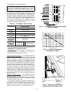
Indoor Air Quality (IAQ) Sensor Input
— The IAQ input
can be used for demand control ventilation control based on the
level of CO
2
measured in the space or return air duct.
Mount the accessory IAQ sensor according to manufacturer
specifications. The IAQ sensor should be wired to the AQ and
AQ1 terminals of the controller. Adjust the DCV potentiome-
ters to correspond to the DCV voltage output of the indoor air
quality sensor at the user-determined set point. See Fig. 43.
If a separate field-supplied transformer is used to power the
IAQ sensor, the sensor must not be grounded or the
EconoMi$erIV control board will be damaged.
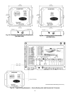
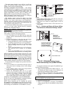
Exhaust Set Point Adjustment
— The exhaust set point will
determine when the exhaust fan runs based on damper position
(if accessory power exhaust is installed). The set point is modi-
fied with the Exhaust Fan Set Point (EXH SET) potentiometer.
See Fig. 36. The set point represents the damper position above
which the exhaust fan will be turned on. When there is a
call for exhaust, the EconoMi$erIV controller provides a
45 ± 15 second delay before exhaust fan activation to allow the
dampers to open. This delay allows the damper to reach the
appropriate position to avoid unnecessary fan overload.
Minimum Position Control
— There is a minimum damper
position potentiometer on the EconoMi$erIV controller. See
Fig. 36. The minimum damper position maintains the mini-
mum airflow into the building during the occupied period.
When using demand ventilation, the minimum damper po-
sition represents the minimum ventilation position for VOC
(volatile organic compound) ventilation requirements. The
maximum demand ventilation position is used for fully occu-
pied ventilation.
When demand ventilation control is not being used, the
minimum position potentiometer should be used to set the oc-
cupied ventilation position. The maximum demand ventilation
position should be turned fully clockwise.
Adjust the minimum position potentiometer to allow the
minimum amount of outdoor air, as required by local codes, to
enter the building. Make minimum position adjustments with
at least 10° F temperature difference between the outdoor and
return-air temperatures.
To determine the minimum position setting, perform the
following procedure:
1. Calculate the appropriate mixed-air temperature using the
following formula:
T
O
= Outdoor-Air Temperature
OA = Percent of Outdoor Air
T
R
= Return-Air Temperature
RA = Percent of Return Air
T
M
= Mixed-Air Temperature
As an example, if local codes require 10% outdoor air
during occupied conditions, outdoor-air temperature is
60 F, and return-air temperature is 75 F.
(60 x .10) + (75 x .90) = 73.5 F
2. Disconnect the supply-air sensor from terminals T and
T1.
3. Ensure that the factory-installed jumper is in place across
terminals P and P1. If remote damper positioning is being
used, make sure that the terminals are wired according to
Fig. 36 and that the minimum position potentiometer is
turned fully clockwise.
4. Connect 24 vac across terminals TR and TR1.
5. Carefully adjust the minimum position potentiometer
until the measured mixed-air temperature matches the
calculated value.
6. Reconnect the supply-air sensor to terminals T and T1.
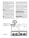
Remote control of the EconoMi$erIV damper is desirable
when requiring additional temporary ventilation. If a
field-supplied remote potentiometer (Honeywell part number
S963B1128) is wired to the EconoMi$erIV controller, the min-
imum position of the damper can be controlled from a remote
location.
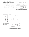
To control the minimum damper position remotely, remove
the factory-installed jumper on the P and P1 terminals on the
EconoMi$erIV controller. Wire the field-supplied potentiome-
ter to the P and P1 terminals on the EconoMi$erIV controller.
See Fig. 40.
Damper Movement
— Damper movement from full open to
full closed (or vice versa) takes 2
1
/
2
minutes.
Thermostats
— The EconoMi$erIV control works with con-
ventional thermostats that have a Y1 (cool stage 1), Y2 (cool
stage 2), W1 (heat stage 1), W2 (heat stage 2), and G (fan). The
EconoMi$erIV control does not support space temperature
sensors. Connections are made at the thermostat terminal con-
nection board located in the main control box.
Occupancy Control
— The factory default configuration for
the EconoMi$erIV control is occupied mode. Occupied status
is provided by the black jumper from terminal TB2-9 to termi-
nal TB2-10. When unoccupied mode is desired, install a field-
supplied timeclock function in place of the jumper between
terminals TB2-9 and TB2-10. See Fig. 36. When the timeclock
contacts are closed, the EconoMi$erIV control will be in occu-
pied mode. When the timeclock contacts are open (removing
the 24-v signal from terminal N), the EconoMi$erIV will be in
unoccupied mode.
Demand Controlled Ventilation (DCV)
— When using the
EconoMi$erIV for demand controlled ventilation, there are
some equipment selection criteria which should be considered.
When selecting the heat capacity and cool capacity of the
equipment, the maximum ventilation rate must be evaluated for
design conditions. The maximum damper position must be cal-
culated to provide the desired fresh air.
(T
O
x
OA
)+(TRx
RA
)=T
M
100 100