


11
Step 3 — Field Fabricate Ductwork — Secure all
ducts to building structure. Use flexible duct connectors be-
tween unit and ducts as required. Insulate and weatherproof all
external ductwork, joints, and roof openings with counter
flashing and mastic in accordance with applicable codes.
Ducts passing through an unconditioned space must be in-
sulated and covered with a vapor barrier.
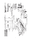
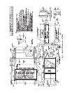
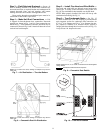
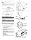
Step 4 — Make Unit Duct Connections — Unit
is shipped for thru-the-bottom duct connections. Ductwork
openings are shown in Fig. 1 and 4-6. Duct connections are
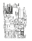
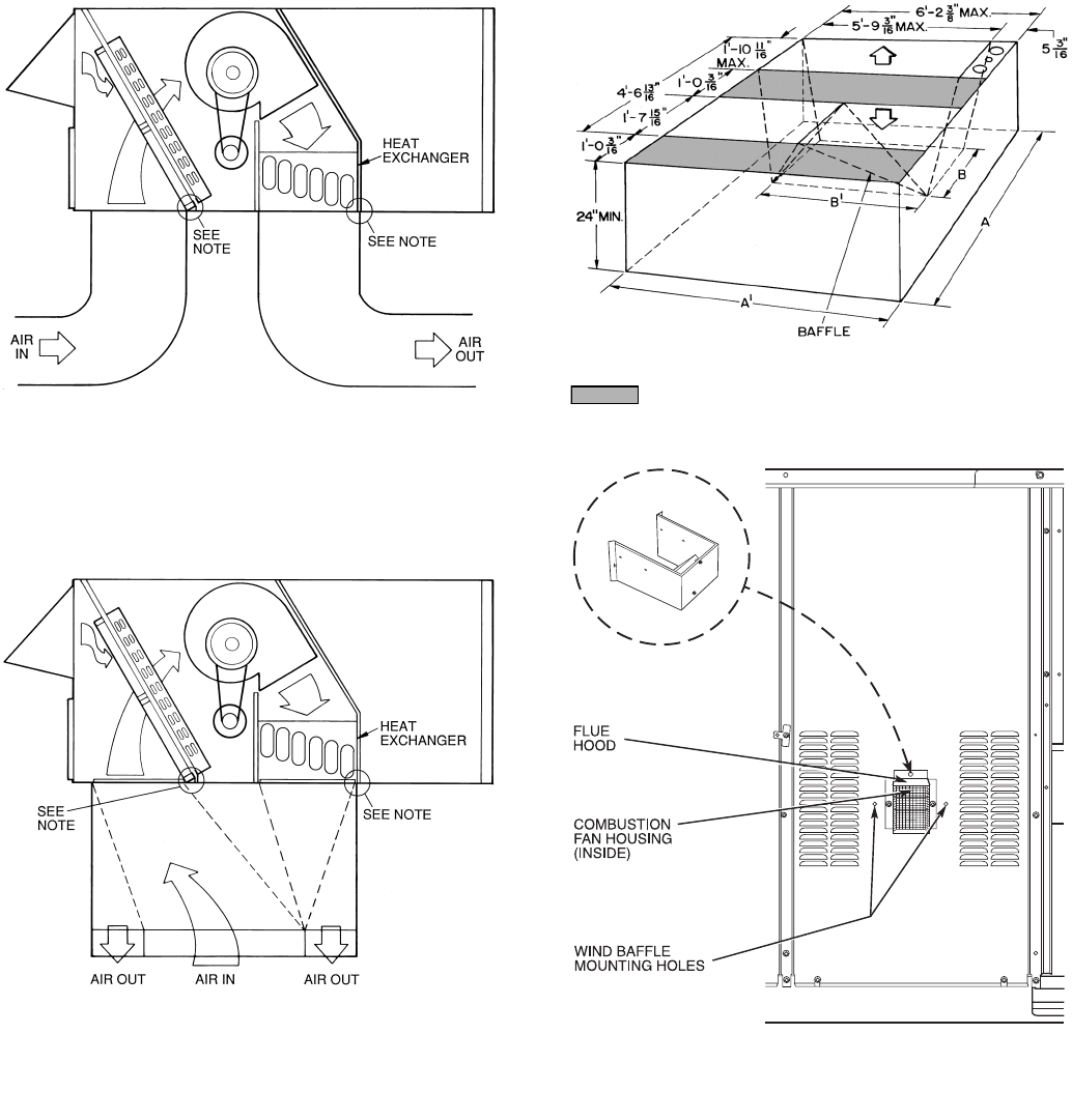
shown in Fig. 7. Field-fabricated concentric ductwork may be
connected as shown in Fig. 8 and 9. Attach all ductwork to roof
curb and roof curb basepans.
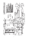
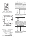
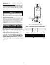
Step 5 — Install Flue Hood and Wind Baffle —
Flue hood and wind baffle are shipped secured under main
control box. To install, secure flue hood to access panel. See
Fig. 10. The wind baffle is then installed over the flue hood.
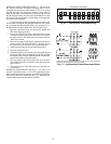
NOTE: When properly installed, flue hood will line up with
combustion fan housing. See Fig. 11.
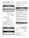
Step 6 — Trap Condensate Drain — See Fig. 12
for drain location. One
3
/
4
-in. half coupling is provided inside
unit evaporator section for condensate drain connection. An
8
1
/
2
-in. x
3
/
4
-in. diameter and 2-in. x
3
/
4
-in. diameter pipe nip-
ple, coupled to standard
3
/
4
-in. diameter elbows, provide a
straight path down through hole in unit base rails (see Fig. 13).
A trap at least 4-in. deep must be used.
WIND
BAFFLE
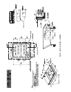
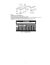
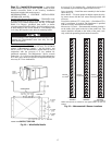
NOTE: Dimensions A, A′, B, and B′ are obtained from field-supplied
ceiling diffuser.
Shaded area indicates block-off panels.
Fig. 9 — Concentric Duct Details
Fig. 10 — Flue Hood Location
NOTE: Do not drill in this area; damage to basepan may result in
water leak.
Fig. 8 — Concentric Duct Air Distribution
NOTE: Do not drill in this area; damage to basepan may result in
water leak.
Fig. 7 — Air Distribution — Thru-the-Bottom