


14
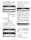
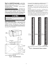
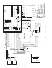
OPTIONAL NON-FUSED DISCONNECT — On units with
the optional non-fused disconnect, incoming power will be
wired into the disconnect switch. Refer to Fig. 17 for wiring
for 100 and 200 amp disconnect switches. Units with an
MOCP (maximum overcurrent protection) under 100 will use
the 100 amp disconnect switch. Units with an MOCP over 100
will use the 200 amp disconnect switch. Refer to the applicable
disconnect wiring diagram.
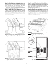
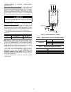
To prevent breakage during shipping, the disconnect han-
dle and shaft are shipped and packaged inside the unit control
box. Install the disconnect handle before unit operation. To in-
stall the handle and shaft, perform the following procedure:
1. Open the control box door and remove the handle and
shaft from shipping location.
2. Loosen the Allen bolt located on the disconnect switch.
The bolt is located on the square hole and is used to hold
the shaft in place. The shaft cannot be inserted until the
Allen bolt is moved.
3. Insert the disconnect shaft into the square hole on the dis-
connect switch. The end of the shaft is specially cut and
the shaft can only be inserted in the correct orientation.
4. Tighten the Allen bolt to lock the shaft into position.
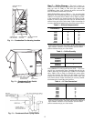
5. Close the control box door.
6. Attach the handle to the external access door with the two
screws provided. When the handle is in the ON position,
thehandlewillbevertical.WhenthehandleisintheOFF
position, the handle will be horizontal.
7. Turn the handle to the OFF position and close the door.
The handle should fit over the end of the shaft when the
door is closed.
8. The handle must be in the OFF position to open the con-
trol box door.
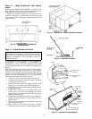
OPTIONAL CONVENIENCE OUTLET — On units with
optional convenience outlet, a 115-v GFI (ground fault inter-
rupt) convenience outlet receptacle is provided for field wiring.
Field wiring should be run through the
7
/
8
-in. knockout pro-
vided in the basepan near the return air opening.
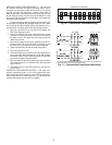
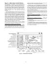
RH
RC
Y1 Y2
W1
W2
GC
X
L
X
C
G
W2
W1Y2
Y1
R
REMOVABLEJUMPER
RED
BLU
PNK
ORN
VIO
BLK
BRN
WHT
THERMOSTATASSEMBLY
5L3 3L2 1L1 LINE
6T3 4T2 2T1 LOAD
Fig. 16 — Field Control Thermostat Wiring
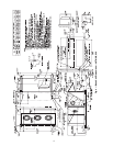
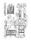
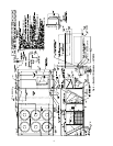
NOTE: The disconnect takes the place of TB-1 as shown on the unit wiring dia
-
gram label and the component arrangement label.
Fig. 17 — Optional Non-Fused Disconnect Wiring