


46
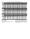
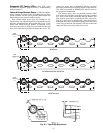
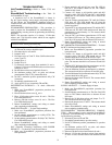
Gas Valve Adjustment
NATURAL GAS — The gas valve opens and closes in
response to the thermostat or limit control.
When power is supplied to valve terminals D1 and C2, the
main valve opens to its preset position.
The regular factory setting is stamped on the valve body
(3.3 in. wg).
To adjust regulator:
1. Set thermostat at setting for no call for heat.
2. Turn main gas valve to OFF position.
3. Remove
1
/
8
-in. pipe plug from manifold or gas valve
pressure tap connection. Install a suitable pressure-
measuring device.
4. Set main gas valve to ON position.
5. Set thermostat at setting to call for heat.
6. Remove screw cap covering regulator adjustment screw
(See Fig. 55).
7. Turn adjustment screw clockwise to increase pressure or
counterclockwise to decrease pressure.
8. Once desired pressure is established, set thermostat set-
ting for no call for heat, turn off main gas valve, remove
pressure-measuring device, and replace
1
/
8
-in. pipe plug
and screw cap.
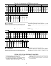
Main Burners — For all applications, main burners are
factory set and should require no adjustment.
MAIN BURNER REMOVAL
1. Shut off (field-supplied) manual main gas valve.
2. Shut off power to unit.
3. Remove unit control box access panel, burner section
access panel, and center post (Fig. 4-6).
4. Disconnect gas piping from gas valve inlet.
5. Remove wires from gas valve.
6. Remove wires from rollout switch.
7. Remove sensor wire and ignitor cable from IGC board.
8. Remove 2 screws securing manifold bracket to basepan.
9. Remove 2 screws that hold the burner support plate
flange to the vestibule plate.
10. Lift burner assembly out of unit.
CLEANING AND ADJUSTMENT
1. Remove burner rack from unit as described in Main
Burner Removal section above.
2. Inspect burners, and if dirty, remove burners from rack.
3. Using a soft brush, clean burners and crossover port as
required.
4. Adjust spark gap. See Fig. 56.
5. Reinstall burners on rack.
6. Reinstall burner rack as described above.
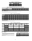
Filter Drier — Replace whenever refrigerant system is
exposed to atmosphere.
Protective Devices
COMPRESSOR PROTECTION
Overcurrent
— Each compressor has internal line break motor
protection.
Crankcase Heater
— All units are equipped with a 70-watt
crankcase heater to prevent absorption of liquid refrigerant by
oil in the crankcase when the compressor is idle. The crank-
case heater is energized whenever there is a main power to the
unit and the compressor is not energized.
Compressor Lockout
— If any of the safeties (high-pressure,
low-pressure, freeze protection thermostat, compressor internal
thermostat) trip, or if there is loss of power to the compressors,
the cooling lockout (CLO) will lock the compressors off. To
reset, manually move the thermostat setting.
EVAPORATOR-FAN MOTOR PROTECTION — A man-
ual reset, calibrated trip, magnetic circuit breaker protects
against overcurrent. Do not bypass connections or increase the
size of the breaker to correct trouble. Determine the cause and
correct it before resetting the breaker.
CONDENSER-FAN MOTOR PROTECTION — Each
condenser-fan motor is internally protected against
overtemperature.
HIGH-PRESSURE AND LOW-PRESSURE SWITCHES —
If either switch trips, or if the compressor overtemperature
switch activates, that refrigerant circuit will be automatically
locked out by the CLO. To reset, manually move the thermo-
stat setting.
FREEZE PROTECTION THERMOSTAT (FPT) — An FPT
is located on the top and bottom of the evaporator coil. They
detect frost build-up and turn off the compressor, allowing the
coil to clear. Once the frost has melted, the compressor can be
reenergized by resetting the compressor lockout.
Relief Devices — All units have relief devices to protect
against damage from excessive pressures (i.e., fire). These
devices protect the high and low side.
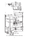
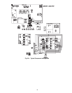
Control Circuit, 24-V — This control circuit is pro-
tected against overcurrent by a 3.2 amp circuit breaker.
Breaker can be reset. If it trips, determine cause of trouble
before resetting. See Fig. 57 and 58 for typical wiring
diagrams.
Replacement Parts — A complete list of replacement
parts may be obtained from any Carrier distributor upon
request.
IMPORTANT: After a prolonged shutdown or servicing,
energize the crankcase heaters for 24 hours before start-
ing the compressors.
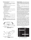
OFF
ON
W-1
W-2
D-1
D-2
C1
C2
PILOT
ADJ.
INLET PRESSURE TAP
(PLUGGED)
1/8 - 27 N.P.T.THDS.
2 LEADS, #18 WIRE 1/32 INSULATION,
600V.MAX., 105°C
REGULATOR
ADJUSTMENT SCREW
(REMOVE COVER)
OUTLET PRESSURE
TAP(PLUGGED)
1/8-27 N.P.T.THDS.
PILOT CONNECTION
FOR 1/4” O.D. TUBING
(PLUGGED)
RECEPTACLEAND
TAB COMBINATION
TERMINAL
RECEPTACLETERMINAL
Fig. 55 — Gas Valve