


27
ECONOMI$ERIV CONTROL MODES
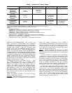
Determine the EconoMi$erIV control mode before set up of
the control. Some modes of operation may require different sen-
sors. Refer to Table 12. The EconoMi$erIV is supplied from the
factory with a supply air temperature sensor, a low temperature
compressor lockout switch, and an outdoor air temperature sen-
sor. This allows for operation of the EconoMi$erIV with out-
door air dry bulb changeover control. Additional accessories
can be added to allow for different types of changeover control
and operation of the EconoMi$erIV and unit.
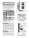
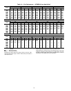
Table 12 — EconoMi$erIV Sensor Usage
*CRENTDIF004A00 and CRTEMPSN002A00 accessories are
used on many different base units. As such, these kits may con-
tain parts that will not be needed for installation.
†33ZCSENCO2 is an accessory CO
2
sensor.
**33ZCASPCO2 is an accessory aspirator box required for duct-
mounted applications.
††CRCBDIOX005A00 is an accessory that contains both
33ZCSENCO2 and 33ZCASPCO2 accessories.
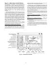
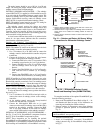
Outdoor Dry Bulb Changeover — The standard controller is
shipped from the factory configured for outdoor dry bulb
changeover control. The outdoor air and supply air temperature
sensors are included as standard. For this control mode, the
outdoor temperature is compared to an adjustable set point
selected on the control. If the outdoor-air temperature is above
the set point, the EconoMi$erIV will adjust the outdoor-air
dampers to minimum position. If the outdoor-air temperature is
below the set point, the position of the outdoor-air dampers will
be controlled to provide free cooling using outdoor air. When
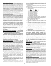
in this mode, the LED next to the free cooling set point potenti-
ometer will be on. The changeover temperature set point is
controlled by the free cooling set point potentiometer located
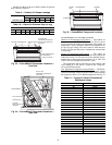
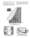
on the control. See Fig. 38. The scale on the potentiometer is A,
B, C, and D. See Fig. 39 for the corresponding temperature
changeover values.
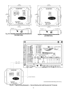
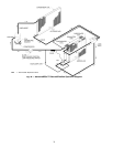
Differential Dry Bulb Control
— For differential dry bulb
control the standard outdoor dry bulb sensor is used in conjunc-
tion with an additional accessory return air sensor (part number
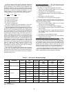
CRTEMPSN002A00). The accessory sensor must be mounted
in the return airstream. See Fig. 40.
In this mode of operation, the outdoor-air temperature is
compared to the return-air temperature and the lower tempera-
ture airstream is used for cooling. When using this mode of
changeover control, turn the free cooling/enthalpy set point
potentiometer fully clockwise to the D setting. See Fig. 38.
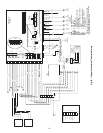
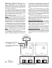
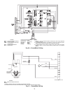
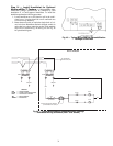
IMPORTANT: The optional EconoMi$er2 does not include
acontroller.TheEconoMi$er2isoperatedbya4to20mA
signal from an existing field-supplied controller (such as
PremierLink™ control). See Fig. 37 for wiring information.
APPLICATION
ECONOMI$ERIV WITH OUTDOOR AIR
DRY BULB SENSOR
Accessories Required
Outdoor Air
Dry Bulb
None. The outdoor air dry bulb sensor
is factory installed.
Differential
Dry Bulb
CRTEMPSN002A00*
Single Enthalpy HH57AC078
Differential
Enthalpy
HH57AC078
and
CRENTDIF004A00*
CO
2
for DCV
Control using a
Wall-Mounted
CO
2
Sensor
33ZCSENCO2
CO
2
for DCV
Control using a
Duct-Mounted
CO
2
Sensor
33ZCSENCO2†
and
33ZCASPCO2**
OR
CRCBDIOX005A00††
Fig. 38 — EconoMi$erIV Controller Potentiometer
and LED Locations
LED ON
LED ON
LED ON
LED ON
LED OFF
19
18
LED OFF
LED OFF
LED OFF
17
16
15
14
13
12
11
10
9
40
45
50
55
60
65
70
75
80
85
90
95
100
DEGREES FAHRENHEIT
mA
D
C
B
A
Fig. 39 — Outside Air Temperature
Changeover Set Points
IAQ
SENSOR
RETURN AIR
TEMPERATURE
OR ENTHALPY
SENSOR
T
R1
2
4
V
a
c
CO
M
T
R
2
4
V
ac
HO
T
1
2
3
4
5
E
F
E
F
1
+
_
P
1
T
1
P
T
N
EX
H
2
V
1
0V
E
XH
S
e
t
S
e
t
2
V
1
0V
2
V
1
0V
D
C
V
D
CV
F
r
e
e
C
ool
B
C
A
D
S
O
+
S
R+
S
R
SO
AQ
1
A
Q
DC
V
M
i
n
P
o
s
O
pe
n
M
ax
N
1
Fig. 40 — Return Air Temperature or
Enthalpy Sensor Mounting Location