


29
Typically the maximum ventilation rate will be about 5 to
10% more than the typical cfm required per person, using
normal outside air design criteria.
A proportional anticipatory strategy should be taken with
the following conditions: a zone with a large area, varied occu-
pancy, and equipment that cannot exceed the required ventila-
tion rate at design conditions. Exceeding the required ventila-
tion rate means the equipment can condition air at a maximum
ventilation rate that is greater than the required ventilation rate
for maximum occupancy. A proportional-anticipatory strategy
will cause the fresh air supplied to increase as the room CO
2
level increases even though the CO
2
set point has not been
reached. By the time the CO
2
level reaches the set point, the
damper will be at maximum ventilation and should maintain
the set point.
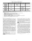
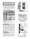
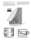
CONTROL
CURVE
A
B
C
D
CONTROL POINT
APPROX. °F (°C)
AT 50% RH
73 (23)
70 (21)
67 (19)
63 (17)
1
2
1
4
1
6
1
8
2
0
2
2
2
4
26
28
30
32
3
4
3
6
3
8
40
42
4
4
46
9
0
1
0
0
80
70
6
0
50
4
0
3
0
20
1
0
E
NT
HA
L
P
Y
—
B
TU
P
E
R
PO
U
N
D
DR
Y A
IR
85
(29)
90
(32)
95
(35)
100
(38)
105
(41)
110
(43)
35
(2)
35
(2)
40
(4)
40
(4)
105
(41)
110
(43)
45
(7)
45
(7)
50
(10)
50
(10)
55
(13)
55
(13)
60
(16)
60
(16)
65
(18)
65
(18)
70
(21)
70
(21)
75
(24)
75
(24)
80
(27)
80
(27)
85
(29)
90
(32)
95
(35)
100
(38)
APPROXIMATE DRY BULB TEMPERATURE— °F (°C)
A
A
B
B
C
C
D
D
R
E
L
A
T
I
VE
H
U
M
ID
IT
Y
(
%
)
HIGH LIMIT
CURVE
Fig. 41 — Enthalpy Changeover Set Points
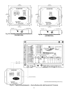
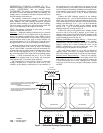
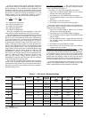
TR1
24 Vac
COM
TR
24
Vac
HOT
12
3
4
5
EF
EF1
+
_
P1
T1
P
T
N
EXH
2V 10V
EXH
Set
Set
2V 10V
2V 10V
DCV
DCV
Free
Cool
B
C
A
D
SO+
SR+
SR
SO
AQ1
AQ
DCV
Min
Pos
Open
Max
N1
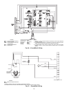
Fig. 42 — EconoMi$erIV Controller
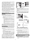
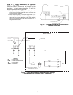
0
1000
2000
3000
4000
5000
6000
2345678
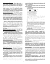
800 ppm
900 ppm
1000 ppm
1100 ppm
RANGE CONFIGURATION (ppm)
DAMPER VOLTAGE FOR MAX VENTILATION RATE
CO SENSOR MAX RANGE SETTING
2
Fig. 43 — CO
2
Sensor Maximum Range Setting