


54
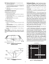
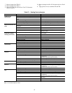
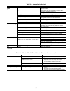
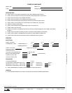
Table 30 — EconoMi$erIV Input/Output Logic
*For single enthalpy control, the module compares outdoor
enthalpy to the ABCD set point.
†Power at N terminal determines Occupied/Unoccupied setting:
24 vac (Occupied), no power (Unoccupied).
**Modulation is based on the supply air sensor signal.
††Modulation is based on the DCV signal.
***Modulation is based on the greater of DCV and supply-air sen-
sor signals, between minimum position and either maximum
position (DCV) or fully open (supply-air signal).
†††Modulation is based on the greater of DCV and supply-air
sensor signals, between closed and either maximum position
(DCV) or fully open (supply-air signal).
INPUTS OUTPUTS
Demand Control
Ventilation (DCV)
Enthalpy*
Y1 Y2
Compressor N Terminal†
Outdoor Return
Stage
1
Stage
2
Occupied Unoccupied
Damper
Below set
(DCV LED Off)
High
(Free Cooling LED Off)
Low On On On On Minimum position Closed
On Off On Off
Off Off Off Off
Low
(Free Cooling LED On)
High On On On Off Modulating** (between min.
position and full-open)
Modulating** (between
closed and full-open)
On Off Off Off
Off Off Off Off Minimum position Closed
Above set
(DCV LED On)
High
(Free Cooling LED Off)
Low On On On On Modulating†† (between min.
position and DCV maximum)
Modulating†† (between
closed and DCV
maximum)
On Off On Off
Off Off Off Off
Low
(Free Cooling LED On)
High On On On Off Modulating*** Modulating†††
On Off Off Off
Off Off Off Off