


43
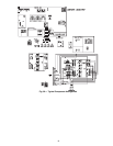
HEATING, UNIT WITH ECONOMI$ER2, PREMIERLINK
CONTROL AND A ROOM SENSOR — Every 40 seconds
the controller will calculate the required heat stages (maximum
of 3) to maintain supply air temperature (SAT) if the following
qualifying conditions are met:
• Indoor fan has been on for at least 30 seconds.
• COOL mode is not active.
• OCCUPIED, TEMP.COMPENSATED START or HEAT
mode is active.
• SAT reading is available.
• Fire shutdown mode is not active.
If all of the above conditions are met, the number of heat
stages is calculated; otherwise the required number of heat
stages will be set to 0.
If the PremierLink controller determines that heat stages are
required, the economizer damper will be moved to minimum
position if occupied and closed if unoccupied.
Staging should be as follows:
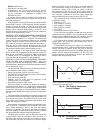
If Heating PID STAGES=2
• HEAT STAGES=1 (75% capacity) will energize HS1
• HEAT STAGES=2 (100% capacity) will energize HS2
In order to prevent short cycling, the unit is locked into the
Heating mode for at least 10 minutes when HS1 is deenergized.
When HS1 is energized the induced-draft motor is then
energized and the burner ignition sequence begins. On units
equipped for two stages of heat, when additional heat is need-
ed, HS2 is energized and the high-fire solenoid on the main gas
valve (MGV) is energized. When the space condition is satis-
fied and HS1 is deenergized the IFM stops after a 45-second
time-off delay unless in the occupied mode. The fan will run
continuously in the occupied mode as required by national
energy and fresh air standards.
SERVICE
Cleaning —
Inspect unit interior at beginning of each
heating and cooling season and as operating conditions require.
Remove unit top panel and/or side panels for access to unit
interior.
MAIN BURNER — At the beginning of each heating season,
inspect for deterioration or blockage due to corrosion or other
causes. Observe the main burner flames. Refer to Main Burn-
ers section on page 46.
FLUE GAS PASSAGEWAYS — The flue collector box and
heat exchanger cells may be inspected by removing heat
exchanger access panel (Fig. 4-6), flue box cover, and main
burner assembly. Refer to Main Burners section on page 46 for
burner removal sequence. If cleaning is required, remove heat
exchanger baffles and clean tubes with a wire brush.
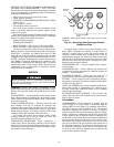
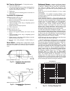
Use caution with ceramic heat exchanger baffles. When
installing retaining clip, be sure the center leg of the clip
extends inward toward baffle. See Fig. 49.
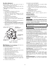
COMBUSTION-AIR BLOWER — Clean periodically to
assure proper airflow and heating efficiency. Inspect blower
wheel every fall and periodically during heating season. For the
first heating season, inspect blower wheel bi-monthly to deter-
mine proper cleaning frequency.
To inspect blower wheel, remove heat exchanger access
panel. Shine a flashlight into opening to inspect wheel. If
cleaning is required, remove motor and wheel assembly by
removing screws holding motor mounting plate to top of
combustion fan housing. The motor and wheel assembly will
slide up and out of the fan housing. Remove the blower wheel
from the motor shaft and clean with a detergent or solvent.
Replace motor and wheel assembly.
EVAPORATOR COIL — Clean as required with a commer-
cial coil cleaner.
CONDENSER COIL — Clean condenser coil annually and
as required by location and outdoor-air conditions. Inspect coil
monthly — clean as required.
CONDENSATE DRAIN — Check and clean each year at
start of cooling season. In winter, keep drains and traps dry.
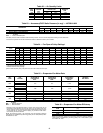
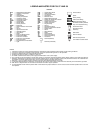
FILTERS — Clean or replace at start of each heating and cool-
ing season, or more often if operating conditions require. Refer
to Table 1 for type and size.
NOTE: The 48TM028 unit requires industrial grade throw-
away filters capable of withstanding face velocities up to
625 fpm. Ensure that replacement filters for the 48TM028
units are rated for 625 fpm.
OUTDOOR-AIR INLET SCREENS — Clean screens with
steam or hot water and a mild detergent. Do not use throwaway
filters in place of screens.
Lubrication
COMPRESSORS — Each compressor is charged with the
correct amount of oil at the factory. Conventional white oil
(Sontext 200LT) is used. White oil is compatible with 3GS oil,
and 3GS oil may be used if the addition of oil is required. See
compressor nameplate for original oil charge. A complete
recharge should be four ounces less than the original oil charge.
When a compressor is exchanged in the field it is possible that
a major portion of the oil from the replaced compressor may
still be in the system. While this will not affect the reliability of
the replacement compressor, the extra oil will add rotor drag
and increase power usage. To remove this excess oil, an access
valve may be added to the lower portion of the suction line at
the inlet of the compressor. The compressor should then be run
for 10 minutes, shut down, and the access valve opened until
no oil flows. This should be repeated twice to make sure the
proper oil level has been achieved.
Before performing service or maintenance operations on
unit, turn off main power switch to unit. Electrical shock
could cause personal injury.
CERAMIC
BAFFLE
CLIP
HEATEXCHANGER
TUBES
NOTE: One baffle and clip will be in each upper tube of the heat
exchanger.
Fig. 49 — Removing Heat Exchanger Ceramic
Baffles and Clips