


17
Step 12 — Install All Accessories — After all the
factory-installed options have been adjusted, install all field-
installed accessories. Refer to the accessory installation
instructions included with each accessory.
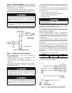
MOTORMASTER® I CONTROL INSTALLATION
(48TM016,020, and 028)
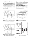
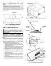
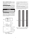
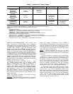
Install Field-Fabricated Wind Baffles
— Wind baffles must
be field-fabricated for all units to ensure proper cooling cycle
operation at low ambient temperatures. See Fig. 22 for baffle
details. Use 20-gage, galvanized sheet metal, or similar
corrosion-resistant metal for baffles. Use field-supplied screws
to attach baffles to unit. Screws should be
1
/
4
-in. diameter and
5
/
8
-in. long. Drill required screw holes for mounting baffles.
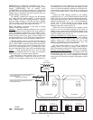
Install Motormaster I Controls — Only one Motormaster I
control is required for 48TM016 and 020 units. The 48TM028
requires 2 Motormaster I controls — one for circuit 1 and
one for circuit 2. The Motormaster I control must be used in
conjunction with the accessory 0° F low ambient kit
(purchased separately). The Motormaster I device controls
outdoor fan no. 1 (and 4 on size 028 units) while outdoor fans
no. 2 and 3 (and 5 and 6 on 028 units) are sequenced off by the
Accessory 0° F Low Ambient Kit.
Accessory 0° F Low Ambient Kit — Install the accessory 0° F
low ambient kit per instruction supplied with accessory.
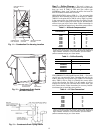
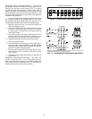
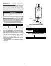
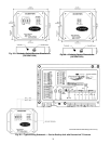
Sensor Assembly — Install the sensor assembly in the location
shown in Fig. 23.
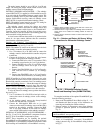
Motor Mount — To ensure proper fan height, replace the exist-
ing motor mount with the new motor mount provided with
accessory.
Transformer (460 and 575-v Units Only) — On 460 and 575-v
units, a transformer is required. The transformer is provided
with the accessory and must be field-installed.
Motormaster I Control — Recommended mounting location is
on the inside of the panel to the left of the control box. The
control should be mounted on the inside of the panel, verti-
cally, with leads protruding from bottom of extrusion.
To avoid damage to the refrigerant coils and electrical com-
ponents, use recommended screw sizes only. Use care
when drilling holes.
NOTE: Dimensions in ( ) are in mm.
Fig. 22 — Wind Baffle Details
SENSOR
LOCATION
HAIRPIN END
SENSOR
LOCATION
HAIRPIN END
SENSOR
LOCATION
HAIRPIN END
48TM016 48TM020 48TM028
(Circuits 1 and 2)
NOTE: All sensors are located on the eighth hairpin up from the
bottom.
Fig. 23 — Motormaster® I Sensor Locations