


2
INSTALLATION
Inspect unit for transportation damage. If damage is found,
file any claim with the transportation agency.
Step 1 — Provide Unit Support
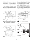
ROOF CURB — Assemble and install accessory roof curb or
horizontal adapter roof curb in accordance with instructions
shipped with this accessory. See Fig. 1-2B. Install insulation,
cant strips, roofing, and counter flashing as shown. Ductwork
can be installed to roof curb or horizontal adapter roof curb be-
fore unit is set in place. Curb or adapter roof curb should be
level. This is necessary to permit unit drain to function proper-
ly. Unit leveling tolerance is ±
1
/
16
in. per linear ft in any direc-
tion. Refer to Accessory Roof Curb or Horizontal Adapter
Roof Curb Installation Instructions for additional information
as required. When accessory roof curb or horizontal adapter
roof curb is used, unit may be installed on class A, B, or C roof
covering material.
ALTERNATE UNIT SUPPORT — When the curb or adapter
cannot be used, install unit on a noncombustible surface. Sup-
port unit with sleepers, using unit curb support area. If sleepers
cannot be used, support long sides of unit with a minimum of
3 equally spaced 4-in. x 4-in. pads on each side.
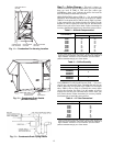
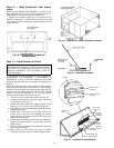
Step 2 — Rig and Place Unit — Do not drop unit;
keep upright. Use spreader bars over unit to prevent sling or ca-
ble damage. Rollers may be used to move unit across a roof.
Level by using unit frame as a reference; leveling tolerance is ±
1
/
16
in. per linear ft in any direction. See Fig. 3 for additional in-
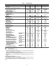
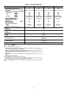
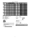
formation. Unit operating weight is shown in Table 1.
Four lifting holes are provided in ends of unit base rails as
shown in Fig. 3. Refer to rigging instructions on unit.
NOTE: On 48TM028 units, the lower forklift braces must
be removed prior to setting unit on roof curb.
POSITIONING — Maintain clearance, per Fig. 4-6, around
and above unit to provide minimum distance from combustible
materials, proper airflow, and service access.
Do not install unit in an indoor location. Do not locate unit
air inlets near exhaust vents or other sources of contaminated
air. For proper unit operation, adequate combustion and venti-
lation air must be provided in accordance with Section 5.3 (Air
for Combustion and Ventilation) of the National Fuel Gas
Code, ANSI Z223.1 (American National Standards Institute).
Although unit is weatherproof, guard against water from
higher level runoff and overhangs.
Locate mechanical draft system flue assembly at least 4 ft
from any opening through which combustion products could
enter the building, and at least 4 ft from any adjacent building.
When unit is located adjacent to public walkways, flue assem-
bly must be at least 7 ft above grade. Locate unit at least 10 ft
away from adjacent units.
ROOF MOUNT — Check building codes for weight distri-
bution requirements. Unit operating weight is shown in
Table 1.
Instructions continued on page 11.
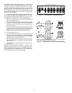
IMPORTANT: The gasketing of the unit to the roof curb
or adapter roof curb is critical for a watertight seal.
Install gasket with the roof curb or adapter as shown in
Fig. 2A and 2B. Improperly applied gasket can also
result in air leaks and poor unit performance.
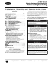
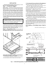
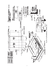
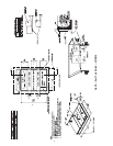
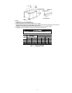
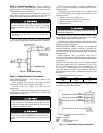
Fig. 1 — Horizontal Supply/Return Adapter Installation (48TM016-025)
NOTE: CRRFCURB013A00 is a fully factory preassembled hori-
zontal adapter and includes an insulated transition duct. The pres-
sure drop through the adapter curb is negligible.
For horizontal return applications: The power exhaust and baro-
metric relief dampers must be installed in the return air duct.
23"
14 3/4"
6"
3 1/2"
FULLYINSULATED
SUPPLYPLENUM
1" INSULATION
1 1/2 # DENSITY,
STICK PINNED & GLUED
2" X 1/4
SUPPORT TYP.
STITCH WELDED
12" WIDE STANDING
SEAM PANELS
ACCESSORY
PACKAGE NO.
CURB
HEIGHT
DESCRIPTION
CRRFCURB013A00
1′-11″
(584)
Pre-Assembled, Roof Curb,
Horizontal Adapter