


23
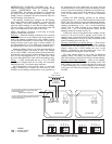
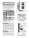
DIFFERENTIAL ENTHALPY CONTROL (Fig. 30) —
Differential enthalpy control requires both an enthalpy switch/
receiver (33CSENTHSW) and an enthalpy sensor
(33CSENTSEN). The enthalpy switch/receiver is mounted in
the outdoor air inlet and calculates outdoor air enthalpy. The
enthalpy sensor is mounted in the return airstream and calcu-
lates the enthalpy of the indoor air.
The enthalpy switch/receiver energizes the HI Enthalpy
relay output when the outdoor enthalpy is greater than the
indoor enthalpy. The LOW Enthalpy terminal is energized
when the outdoor enthalpy is lower than the indoor enthalpy.
The relay output is wired to the unit economizer which will
open or close depending on the output of the switch.
NOTE: The enthalpy calculation is done using an average
altitude of 1000 ft above sea level.
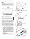
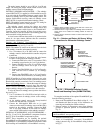
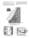
Mounting
— Mount the enthalpy switch/receiver in a location
where the outdoor air can be sampled (such as the outdoor air
intake). The enthalpy switch/receiver is not a NEMA 4 enclo-
sure and should be mounted in a location that is not exposed to
outdoor elements such as rain, snow, or direct sunlight. Use
two field-supplied no. 8 x
3
/
4
-in. TEK screws. Insert the screws
through the holes in the sides of the enthalpy switch/receiver.
Mount the enthalpy sensor in a location where the indoor air
can be sampled (such as the return air duct). The enthalpy
sensor is not a NEMA 4 enclosure and should be mounted in a
location that is not exposed to outdoor elements such as rain or
snow. Use two field-supplied no. 8 x
3
/
4
-in. TEK screws. Insert
the screws through the holes in the sides of the enthalpy sensor.
Wiring
— Carrier recommends the use of 18 to 22 AWG
twisted pair or shielded cable for all wiring. All connections
must be made with
1
/
4
-in. female spade connectors.
The PremierLink™ board provides 24-vac to power the
enthalpy switch/receiver. Connect the GND and 24 VAC
terminals on the enthalpy switch/receiver to the terminals on
the transformer. On some applications, the power from the
economizer harness can be used to power the enthalpy switch/
receiver. To power the enthalpy switch/receiver from the econ-
omizer harness, connect power of the enthalpy switch/receiver
to the red and brown wires (1 and 4) on the economizer
harness.
Connect the LOW Enthalpy terminal on the enthalpy
switch/receiver to J4 — pin 2 of the PremierLink control on the
HVAC unit. The switch can be powered through the Premier-
Link control board if desired. Wire the 24VAC terminal on the
enthalpy switch/receiver to J4 — pin 1 on the PremierLink
control. Wire the GND terminal on the enthalpy switch/
receiver to J1 — pin 2 on the PremierLink control. The HI
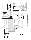
Enthalpy terminal is not used. See Fig. 29.
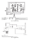
Connect the 4-20 mA IN terminal on the enthalpy switch/
receiver to the 4-20 mA OUT terminal on the return air
enthalpy sensor. Connect the 24-36 VDC OUT terminal on the
enthalpy switch/receiver to the 24-36 VDC IN terminal on the
return air enthalpy sensor. See Fig. 30.
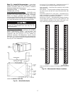
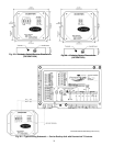
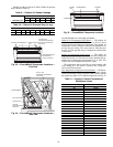
Enthalpy Switch/Receiver Jumper Settings
—Therearetwo
jumpers. One jumper determines the mode of the enthalpy
switch/receiver. The other jumper is not used. To access the
jumpers, remove the 4 screws holding the cover on the
enthalpy switch/receiver and then remove the cover. The
factory settings for the jumpers are M1 and OFF.
The mode jumper should be set to M2 for differential
enthalpy control. The factory test jumper should remain on
OFF or the enthalpy switch/receiver will not calculate enthalpy.
Enthalpy Sensor Jumper Settings
— There are two jumpers.
One jumper determines the mode of the enthalpy sensor. The
other jumper is not used. To access the jumpers, remove the
4 screws holding the cover on the enthalpy sensor and then
remove the cover. The factory settings for the jumpers are M3
and OFF.
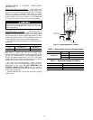
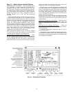
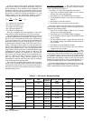
Fig. 30 — Differential Enthalpy Control Wiring
24 VAC OUTPUT FROM N/C CONTACTWHEN THE
OUTDOOR ENTHALPY IS LESSTHAN THE
INDOOR ENTHALPY
(ENABLE ECONOMIZER)
24 VAC OUTPUT FROM N/O CONTACTWHEN THE
INDOOR ENTHALPY IS GREATERTHAN THE
OUTDOOR ENTHALPY
24 VAC
SECONDARY
HI
LOW
GND 24
VAC
ENTHALPY
4-20
mA
IN
24-36
VDC
OUT
JUMPER SETTINGS FOR 33CSENTHSW
M1
M2
M3
0%
50%
100%
OFF
33CSENTHSW
JUMPER SETTINGS FOR 33CSENTSEN
M1
M2
M3
0%
50%
100%
OFF
33CSENTSEN
24-36
VDC
IN
ORN
120 VAC
LINE VOLTAGE
4-20
mA
OUT
LEGEND
N/C — Normally Closed
N/O — Normally Open