


50
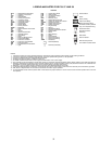
AHA — Adjustable Heat Anticipator
C—Contactor, Compressor
CAP — Capacitor
CB — Circuit Breaker
CC — Cooling Compensator
CH — Crankcase Heater
CLO — Compressor Lockout
COMP — Compressor Motor
CR — Control Relay
DM — Damper Motor
DU — Dummy Terminal
EQUIP — Equipment
FPT — Freeze Protection Thermostat
FU — Fuse
GND — Ground
HPS — High-Pressure Switch
HS — Hall Effect Sensor
HV — High Voltage
I—Ignitor
IAQ — Indoor Air Quality Sensor
IDM — Induced-DraftMotor
IFC — Indoor-Fan Contactor
IFCB — Indoor-Fan Circuit Breaker
IFM — Indoor-Fan Motor
IGC — Integrated Gas Unit Controller
L—Light
LED — Light-Emitting Diode
LOR — LockoutRelay
LPS — Low-Pressure Switch
LS — Limit Switch
MGV — Main Gas Valve
NEC — National Electrical Code
OAT — Outdoor Air Temperature Sensor
OCCUP — Occupancy Sensor
OFC — Outdoor-Fan Contactor
OFM — Outdoor-Fan Motor
PL — Plug Assembly
PRI — Primary
QT — Quadruple Terminal
RAT — Return Air Temperature Sensor
RS — Rollout Switch
SN — Sensor
SR — Solenoid Relay
SW — Switch
TB — Terminal Block
TC — Thermostat Cooling
TH — Thermostat Heating
TRAN — Transformer
Terminal (Marked)
Terminal (Unmarked)
Te r m in al Blo ck
Splice
Factory Wiring
Field ControlWiring
Option/Accessory Wiring
Toindicatecommonpotential
only; not to represent wiring.
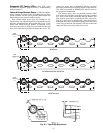
Economizer Motor
Remote POT Field
Accessory
OAT Sensor
Disch Air Sensor
RAT Accessory Sensor
Low Ambient Lockout Switch
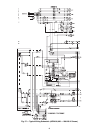
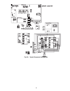
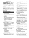
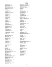
LEGEND AND NOTES FOR FIG. 57 AND 58
LEGEND
NOTES:
1. Compressorand/orfan motor(s) thermally protected. Three-phasemotors protectedagainst primary single phasing conditions.
2. If any of the original wire furnished must be replaced, it must be replaced with Type 90° C or its equivalent.
3. Jumpers are omitted when unit is equipped with economizer.
4. IFCB must trip amps is equal to or less than 140% FLA.
5. On TRAN1 use BLK lead for 460-v power supply and ORN lead for 575-v power supply.
6. The CLO locksout the compressorto preventshort cycling on compressoroverload andsafety devices; before replacingCLO checkthesedevices.
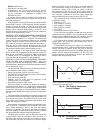
7. Number(s) indicates the line location of used contacts. A bracket over (2) numbers signifies a single pole, double throw contact. An underlined num-
ber signifies a normally closed contact. Plain (no line) number signifies a normally open contact.
8. 620 Ohm, 1 watt, 5% resistor should be removed only when using differential enthalpy or dry bulb.
9. If a separate field supplied 24 v transformer is used for the IAQ sensor power supply,it cannot have the secondary of the transformer grounded.
10. OAT sensor is shippedinsideunit and mustbe relocatedin the field for proper operation.
11. For field installed remote minimum position POT. remove black wire jumper between P and P1 and set control minimum position POT to the mini-
mum position.