


21
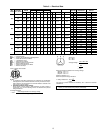
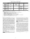
Table 8 — PremierLink™ Sensor Usage
*PremierLink control requires supply air temperature sensor 33ZCSENSAT and
outdoor air temperature sensor HH79NZ039 — Included with factory-installed PremierLink control;
field-supplied and field-installed with field-installed PremierLink control.
NOTES:
1. CO
2
Sensors (Optional):
33ZCSENCO2 — Room sensor (adjustable). Aspirator box is required for duct mounting of the sensor.
33ZCASPCO2 — Aspirator box used for duct-mounted CO
2
room sensor.
33ZCT55CO2 — Space temperature and CO
2
room sensor with override.
33ZCT56CO2 — Space temperature and CO
2
room sensor with override and setpoint.
2. All units include the following standard sensors:
Outdoor-air sensor — 50HJ540569 — Opens at 67 F, closes at 52 F, not adjustable.
Mixed-air sensor — HH97AZ001 — (PremierLink control requires supply air temperature sensor 33ZCSENSAT
and outdoor air temperature sensor HH79NZ039)
Compressor lockout sensor — 50HJ540570 — Opens at 35 F, closes at 50 F.
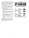
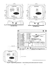
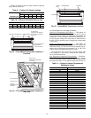
ENTHALPY SWITCH/RECEIVER — The accessory en-
thalpy switch/receiver (33CSENTHSW) senses temperature
and humidity of the air surrounding the device and calculates
theenthalpywhenusedwithoutanenthalpysensor.Therelayis
energized when enthalpy is high and deenergized when
enthalpy is low (based on ASHRAE [American Society of
Heating, Refrigeration and Air Conditioning Engineers] 90.1
criteria). If an accessory enthalpy sensor (33CSENTSEN) is
attached to the return air sensor input, then differential enthalpy
is calculated. The relay is energized when the enthalpy detected
by the return air enthalpy sensor is less than the enthalpy at the
enthalpy switch/receiver. The relay is deenergized when the
enthalpy detected by the return air enthalpy sensor is greater
than the enthalpy at the enthalpy switch/receiver (differential
enthalpy control). See Fig. 27 and 28.
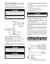
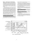
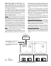
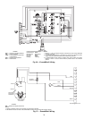
OUTDOOR ENTHALPY CONTROL (Fig. 29) — Out-
door enthalpy control requires only an enthalpy switch/
receiver (33CSENTHSW). The enthalpy switch/receiver is
mounted in the outdoor air inlet and calculates outdoor air
enthalpy. The enthalpy switch/receiver energizes the relay
output when the outdoor enthalpy is above 28 BTU/lb OR dry
bulb temperature is above 75 F and is deenergized when
the outdoor enthalpy is below 27 BTU/lb AND dry bulb
temperature is below 74.5 F. The relay output is wired to the
unit economizer which will open or close depending on the
output of the switch.
NOTE: The enthalpy calculation is done using an average
altitude of 1000 ft above sea level.
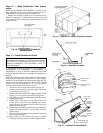
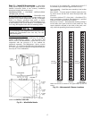
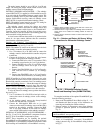
Mounting
— Mount the enthalpy switch/receiver in a location
where the outdoor air can be sampled (such as the outdoor air
intake). The enthalpy switch/receiver is not a NEMA 4
(National Electrical Manufacturers Association) enclosure and
should be mounted in a location that is not exposed to outdoor
elements such as rain or snow. Use two field-supplied no. 8 x
3
/
4
-in. TEK screws. Insert the screws through the holes in the
sides of the enthalpy switch/receiver.
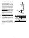
Wiring
— Carrier recommends the use of 18 to 22 AWG
(American Wire Gage) twisted pair or shielded cable for all
wiring. All connections must be made with
1
/
4
-in. female spade
connectors.
A 24-vac transformer is required to power the enthalpy
switch/receiver; as shown in Fig. 29, the PremierLink™ board
provides 24 vac. Connect the GND and 24 VAC terminals on
the enthalpy switch/receiver to the terminals on the transform-
er. On some applications, the power from the economizer
harness can be used to power the enthalpy switch/receiver. To
power the enthalpy switch/receiver from the economizer
harness, connect power of the enthalpy switch/receiver to the
red and brown wires (1 and 4) on the economizer harness.
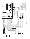
For connection to rooftop units with PremierLink™ control,
connect the LOW Enthalpy terminal on the enthalpy switch/
receiver to J4 — pin 2 of the PremierLink control on the
HVAC unit. The switch can be powered through the Premier-
Link control board if desired. Wire the 24 VAC terminal on the
enthalpy switch/receiver to J4 — pin 1 on the PremierLink
control. Wire the GND terminal on the enthalpy switch/
receiver to J1 — pin 2 on the PremierLink control. The HI
Enthalpy terminal is not used. See Fig. 29.
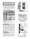
APPLICATION
OUTDOOR AIR
TEMPERATURE SENSOR
RETURN AIR
TEMPERATURE SENSOR
OUTDOOR AIR
ENTHALPY SENSOR
RETURN AIR
ENTHALPY SENSOR
Differential Dry Bulb
Temperature with
PremierLink*
(PremierLink
requires 4-20 mA
Actuator)
Included —
HH79NZ039
Required —
33ZCT55SPT
or Equivalent
——
Single Enthalpy with
PremierLink*
(PremierLink
requires 4-20 mA
Actuator)
Included —
Not Used
—
Required —
33CSENTHSW
(HH57ZC003)
or
HH57AC077
—
Differential Enthalpy
with PremierLink*
(PremierLink
requires 4-20 mA
Actuator)
Included —
Not Used
—
Required —
33CSENTHSW
(HH57ZC003)
or
HH57AC077
Required —
33CSENTSEN
or
HH57AC078