


12
Step 7 — Orifice Change — This unit is factory as-
sembled for heating operation using natural gas at an elevation
from sea level to 2000 ft. This unit uses orifice type
LH32RFnnn, where “nnn” indicates the orifice size based on
drill size diameter in thousands of an inch.
HIGH ELEVATION (Above 2000 ft) — Use accessory high
altitude kit when installing this unit at an elevation of 2000 to
7000 ft. For elevations above 7000 ft, refer to Table 2 to identi-
fy the correct orifice size for the elevation. See Table 3 for the
number of orifices required for each unit size. Purchase these
orifices from your local Carrier dealer. Follow instructions in
accessory Installation Instructions to install the correct orifices.
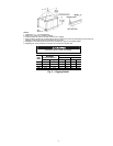
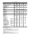
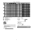
Table 2 — Altitude Compensation*
*As the height above sea level increases, there is less oxygen per
cubic foot of air. Therefore, heat input rate should be reduced at
higher altitudes. Includes a 4% input reduction per each 1000 ft.
†Orifices available through your Carrier dealer.
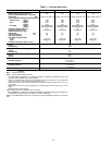
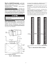
Table 3 — Orifice Quantity
CONVERSION TO LP (Liquid Propane) GAS — Use acces-
sory LP gas conversion kit when converting this unit for use
with LP fuel usage for elevations up to 7000 ft. For elevations
above 7000 ft, refer to Table 4 to identify the correct orifice
size for the elevation. See Table 3 for the number of orifices
required for each unit size. Purchase these orifices from your
local Carrier dealer. Follow instructions in accessory Installa-
tion Instructions to install the correct orifices.
Table 4 — LP Gas Conversion*
*As the height above sea level increases, there is less oxygen per
cubic foot of air. Therefore, heat input rate should be reduced at
higher altitudes. Includes a 4% input reduction per each 1000 ft.
†Orifices available through your Carrier dealer.
ELEVATION (ft)
NATURAL GAS ORIFICE†
Low Heat High Heat
0-1,999 30 29
2,000 30 29
3,000 31 30
4,000 31 30
5,000 31 30
6,000 31 30
7,000 32 31
8,000 32 31
9,000 33 31
10,000 35 32
UNIT ORIFICE QUANTITY
48TMD016 5
48TMD020,
48TMD024,
48TMD028,
48TMF016
6
48TMF020,
48TMF024,
48TMF028
7
ELEVATION (ft) LP GAS ORIFICE†
0-1,999 36
2,000 37
3,000 38
4,000 38
5,000 39
6,000 40
7,000 41
8,000 41
9,000 42
10,000 43
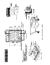
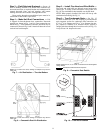
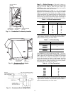
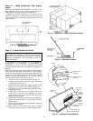
INDUCED DRAFT
MOTOR
MAIN BURNER
SECTION
COMBUSTION
FAN HOUSING
HEATEXCHANGER
SECTION
Fig. 11 — Combustion Fan Housing Location
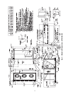
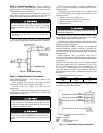
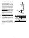
3/4" FPT DRAIN
CONNECTION
1-3/8"
DRAIN HOLE
Fig. 12 — Condensate Drain Details
(48TM016 Shown)
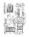
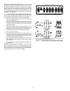
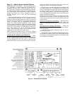
Fig. 13 — Condensate Drain Piping Details