


9
6. Lift boiler with pry bar. Remove wood blocks.
Lower boiler.
C. For Packaged Boiler only, proceed to Paragraph E.
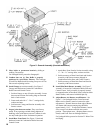
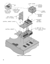
D. Test Section Assembly for leaks before connecting to
system and installing controls, trim and jacket. Refer to
Figure 3 and Table 3.
1. Plug Tappings C & E (¾ NPT) and Return Tapping
B (2 NPT).
2. Insert ¾” NPT x ¼” NPT bushing in Tapping D.
Install pressure gauge capable of indicating 50 psi.
3. Insert 2” NPT x ¾” NPT bushing in Supply Tapping
A. Install purge valve with a hose that runs to a
drain.
4. Connect ll valve and piping to Drain Tapping G.
WARNING
Do not use air to leak test boiler.
5. Fill boiler completely with water by venting air
through purge valve. Close purge valve and apply
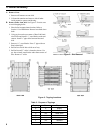
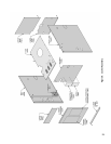
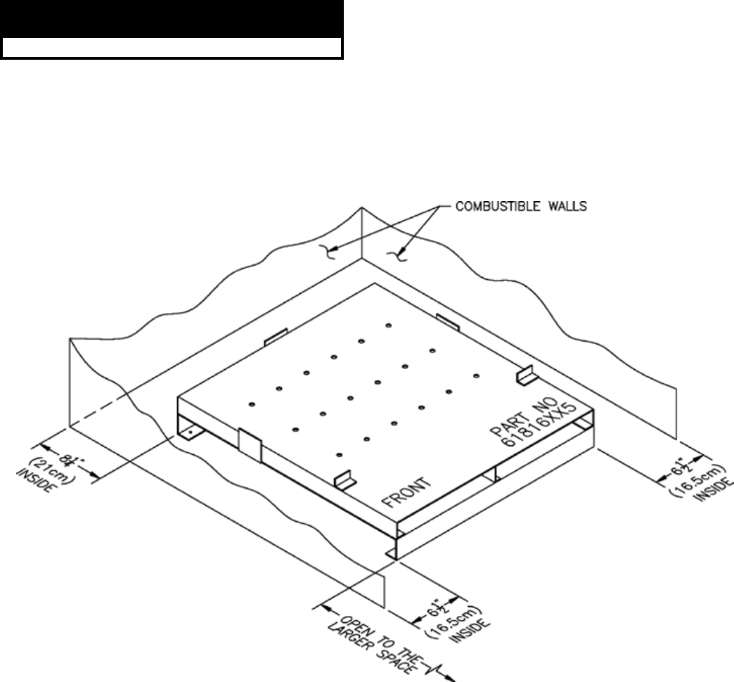
Figure 4: Installation of Special Base for Combustible Flooring
water pressure of at least 10 psi but less than 50 psi
gauge pressure.
6. Examine boiler for leaks or damage due to shipment
or handling.
7. Remove plugs from Return Tapping B, Tapping C,
and Tapping E (if second limit or operating control
is used). Also remove ll valve and piping, purge
valve and piping, and pressure gauge.
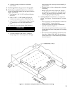
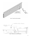
E. Install special base if installation is on combustible
ooring. See Figure 4. Floor shield adds 4¾” to boiler
height.
1. Place special base on combustible oor with surface
marked “FRONT” in upward position.
2. Locate special base with spacing to combustible
materials as shown in Figure 4.
3. Place boiler on special base. Boiler must rest inside
locating brackets. Boiler jacket panels will overhang
special base.
4. Do not enclose boiler (including special base) on all
four sides. Models 805H - 807H may be enclosed
on three sides (alcove) while maintaining clearances
shown in Figure 4.