


10
F. Move boiler to permanent location by sliding or
walking. Do not drop.
For Packaged Boiler, proceed to Paragraph L.
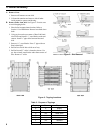
G. Conrm that one (1) Flue Bafe is properly
positioned in each Boiler Flueway. Tabs at the top
of each Flue Bafe should be resting on top row of Flue
Pins on each adjoining section.
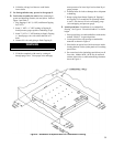
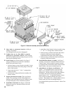
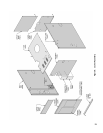
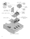
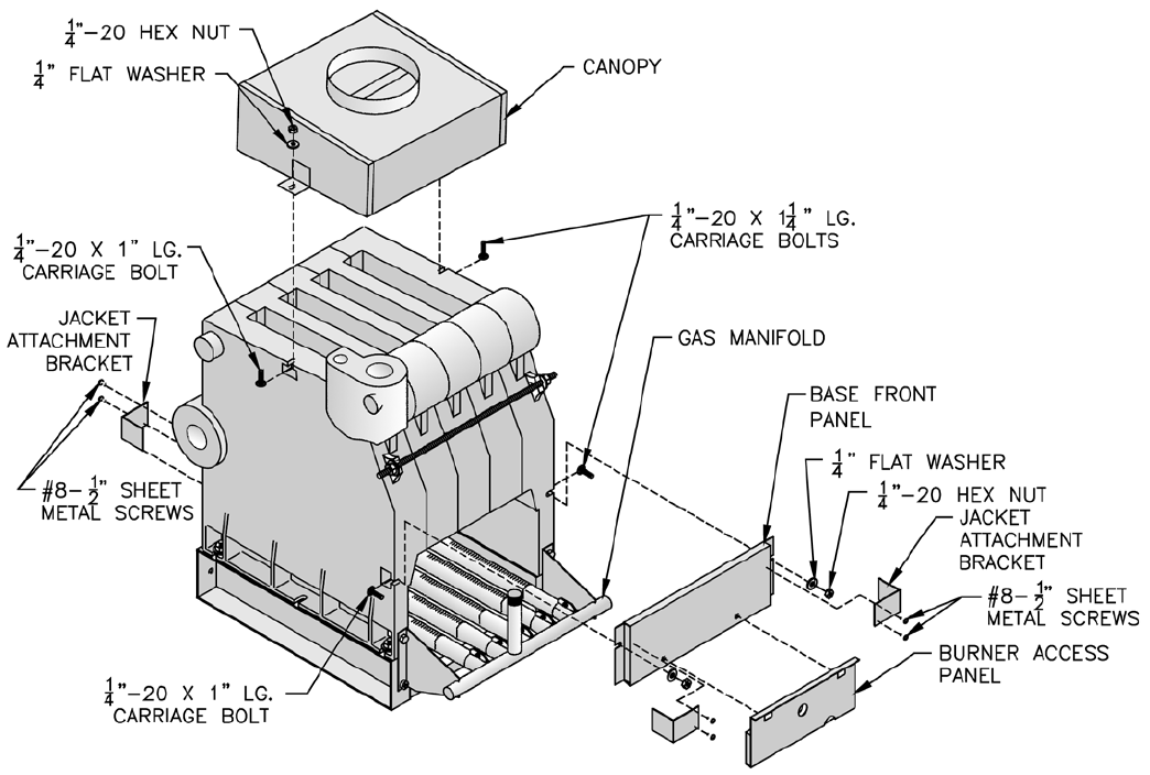
H. Install Canopy on section assembly. See Figure 5.
Canopy and hardware are located in Combination
Boiler Parts and Control Carton.
1. Position Canopy on top of Section Assembly. Locate
between end sections and sealing ledge on front and
back of each section.
2. Fasten each end with ¼” - 20 x 1” carriage bolts,
washers and nuts.
3. Seal between Canopy and Section Assembly with
furnace cement.
I. Inspect joints between sections. They were factory
sealed. If any openings resulted during shipment or
handling, reseal with furnace cement. Conrm tie rods
are only hand tight to allow for thermal expansion.
J. Install Base Front Panel. See Figure 5. Panel and
hardware located in Combination Boiler Parts and
Control Carton.
1. Attach Base Front Panel to Section Assembly using
¼” - 20 x 1¼” carriage bolts, washers and nuts.
2. Seal between top of Base Front Panel and Section
Assembly with furnace cement (shipped in
Combination Boiler Parts and Control Carton).
3. Seal between top of Base Rear Panel and Section
Assembly with furnace cement.
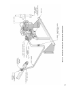
K. Install Pilot/Main Burner Assembly. See Figure 7.
Assembly is located in Combination Boiler Parts and
Control Carton. Verify assembly is properly located
on support bracket in Base Rear Panel, seated on Main
Burner Orice, and secured with hitch pin clip.
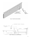
L. Adjust Burner Air Shutters on all Burners. See
Figure 7. (On Packaged Boilers, Front Door and
Burner Access Panel(s) must be removed to make
adjustments.) Distance between front edge of Burner
Air Shutter and burner mounting ring should be
approximately 11/16”. To adjust this distance, loosen
screw at top of air shutter and slide into correct
position. Then tighten screw. (Replace Burner Access
Panel(s) and Front Door on Packaged Boilers.)
For Packaged Boiler, proceed to Section IV: Water Trim
and Piping.
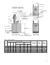
Figure 5: General Assembly (Knockdown Boilers)